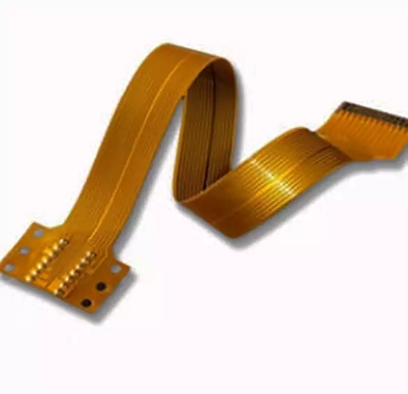
What is a Flexible PCB? Flexible Circuit board, also known as a flexible printed circuit board, is abbreviated as FPC. It is manufactured by transferring and etching conductor patterns onto a flexible substrate surface using photolithography techniques. In double-sided and multilayer boards, metallized vias connect the outer and inner layers electrically. The circuit patterns are protected and insulated by a polyimide (PI) layer and adhesive coating.
Flexible pcbs are primarily categorized into single-sided boards, blind/through-hole boards, double-sided boards, multilayer boards, and rigid-flex boards.
FPC Manufacturing Process:
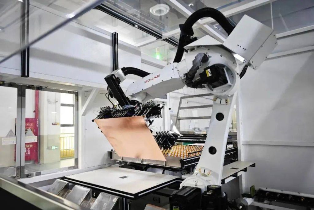
Material Cutting
Flexible substrates are typically supplied in roll form and must be cut into individual boards according to Manufacturing Instructions (MI) specifications.
CNC Drilling
CNC equipment creates through-holes or positioning holes in the substrate, providing pathways for subsequent copper plating to achieve electrical connection between the top and bottom copper layers.
Black Hole Treatment and Electroplating
Post-drilling, the board requires black hole treatment to form a conductive layer since the top and bottom copper layers are not yet connected. Electrochemical deposition then plated copper onto the hole walls, completing the electrical connection between both copper layers.
Dry Film Laminating and Pattern Transfer
Press a photosensitive dry film onto the plated board surface. Use photolithography to precisely transfer circuit patterns onto the dry film layer.
Development, Etching, and Film Removal
Development: Remove unexposed dry film to expose copper foil for etching.
Etching: Chemically etch the exposed copper foil.
Film Removal: Stripping the dry film from circuit pattern areas using sodium hydroxide solution to form the final circuit structure.
Cover Film Laminating
To protect circuits and prevent oxidation-induced shorts, an insulating cover film is laminated. This process involves pre-cutting copper-exposed pads in the cover film before precisely laminating it onto the etched board surface. Cover film colors include yellow, black, and white.
Gold Plating Surface Treatment
The FPC surface undergoes electroless gold plating: a nickel layer is deposited first, followed by a 1μm or 2μm thick gold layer to prevent pad oxidation and enhance soldering reliability.
Character Marking Printing
Customer-specified characters are printed onto the board surface using inkjet technology. The ink is cured via baking to prevent peeling.
Electrical Performance Testing
A flying probe tester is used to verify board conductivity, focusing on detecting defects such as open circuits and short circuits.
Reinforcement
Apply auxiliary materials per customer requirements, including PI reinforcement sheets, electromagnetic shielding films, FR4 reinforcement plates, steel sheets, and adhesive-backed materials.
Laser Contour Cutting
Precisely shape board outlines using laser cutting technology to separate scrap and achieve final product contours.
Final Inspection & Packaging
Conduct comprehensive testing based on customer specifications or IPC standards, screening out non-conforming items with cosmetic defects to ensure compliance with quality standards.
FPC (Flexible Printed Circuit) primarily consists of the following materials: substrate (e.g., polyimide PI, polyester PET), cover film, reinforcement materials (including FR4, steel foil, polyimide PI, etc.), and other auxiliary materials (e.g., adhesives, electromagnetic shielding film). The properties of the substrate determine the flexibility and electrical performance of the FPC.
Substrate: As the foundational layer of FPC, flexible film materials like polyimide (PI) or polyester (PET) are typically selected.
Cover Film: Primarily protects circuit patterns while enhancing insulation properties.
Reinforcement Materials: Designed to improve the mechanical strength and durability of FPC.
Other Auxiliary Materials: Such as adhesives and conductive materials, which play a crucial role in ensuring smooth FPC manufacturing and stable performance.
Advantages of Flexible PCB
- Capable of free bending, rolling, and folding, allowing arbitrary spatial arrangement according to layout requirements. They can move and expand/contract freely in three-dimensional space, achieving integrated component assembly and wire connections.
- Significantly reduces the size and weight of electronic products, meeting the industry’s demand for high-density, miniaturization, and high reliability. Consequently, FPCs are widely adopted in aerospace, military, mobile communications, laptops, computer peripherals, PDAs, digital cameras, and related products;
- FPC also offers excellent heat dissipation, solderability, ease of assembly, and lower overall costs. Rigid-flex designs partially compensate for the slight limitations in component load-bearing capacity inherent to flexible substrates.
Flexible pcb has the following limitations:
High initial investment costs: Flexible PCBs are designed and manufactured for specific application scenarios, requiring significant upfront expenses for circuit design, routing, and photomask production. Therefore, unless specific application requirements mandate their use, flexible PCBs are generally not recommended for low-volume applications.
Difficult to modify and repair: Once manufactured, modifying a flexible PCB necessitates revisiting the original design drawings or plotting programs, making the process highly complex. Additionally, the protective film covering the surface must be removed before repairs and reapplied afterward, presenting significant challenges.
Limited Size Specifications: Given the current limited adoption of flexible PCBs, production often relies on batch processes. This restricts product dimensions to the specifications of manufacturing equipment, preventing the production of excessively long or wide flexible circuit boards.
Susceptibility to Damage from Operational Errors: During assembly, improper handling by technicians can easily damage the flexible pcb. Consequently, operations such as soldering and rework must be performed by professionally trained personnel.