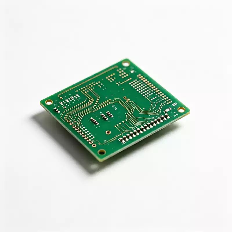
Automotive PCB design is not consumer PCB design with tighter tolerances. The environment inside a vehicle destroys boards that would run flawlessly in a laptop, and the standards governing safety-related electronics leave no room for “close enough.” This guide covers what actually separates an automotive-qualified board from an ordinary one: the operating environment, the standards, the materials, the design rules, and the manufacturing discipline behind them.
Why automotive pcb environments break ordinary PCBs
A consumer PCB lives a pampered life: room temperature, no vibration, low humidity. An automotive PCB survives a temperature swing from -40°C underhood in winter to 125°C or more next to a running engine, constant road vibration, humidity cycles, salt spray on underbody modules, and thermal shock every time the vehicle starts.
The failure modes are well documented. Vibration and mechanical stress alone account for roughly 20% of automotive PCB field failures, showing up as cracked solder joints and fractured traces months after deployment. Thermal cycling causes expansion and contraction that fatigues solder joints and can delaminate substrates. Moisture combined with contamination drives corrosion and electromigration.
One public case shows how expensive these failures get. NHTSA recall 25V-125, filed in early 2025, covered 13,769 Volkswagen ID.4 and Audi Q4 e-tron vehicles after condensation combined with insufficient protective coating on an onboard charger’s DC-DC converter caused electromigration. The result was loss of 12V charging and potential loss of motive power. No exotic component failed. A coating coverage decision did.
That is the automotive reality: the board is a structural, thermal, and chemical system, not just a wiring pattern.
Four standards frameworks show up in every serious automotive PCB program. Each governs a different layer of the problem.
| Standard | Scope | Applicable Party |
|---|---|---|
| ISO 26262 | Functional safety of electrical and electronic systems for road vehicles; risk levels classified as ASIL A ~ D | System and PCB designers for safety-related functions |
| IPC-6012DA | Qualification and performance specification for rigid PCBs for automotive applications | PCB manufacturers |
| AEC-Q100 / AEC-Q200 | Stress test qualification for automotive-grade ICs and passive components | Component suppliers |
| IATF 16949 | Quality management system covering design, fabrication and assembly | Manufacturers |
ISO 26262 deserves special attention because it changes how the board is designed, not just how it is documented. Braking, steering, and other safety-critical systems fall under ASIL B or D requirements, which means the PCB must support fault detection, fault tolerance, and redundancy. A single-point failure that would be a nuisance in an infotainment system is unacceptable in a braking controller.
ISO 16750 adds the environmental dimension: high and low temperature cycling, vibration and shock, salt spray, damp heat, and voltage fluctuation testing. If a board cannot pass simulated environment testing, its signal integrity never gets evaluated.
A practical distinction worth internalizing: AEC-Q100 qualifies the chips, not the board they sit on. IPC-6012DA qualifies the board. IATF 16949 qualifies the process that made it. All three have to line up.
Material selection for automotive PCBs
Material choice is where thermal and mechanical reliability is won or lost. The key parameters are glass transition temperature (Tg), decomposition temperature (Td), and Z-axis coefficient of thermal expansion (CTE).
| Material | Tg (°C) | Typical Automotive Application |
|---|---|---|
| High-Tg FR-4 | ≥170 | Infotainment, body electronics, cost-sensitive modules |
| Halogen-free High-Tg FR-4 | 173–190 | Camera modules, ECUs, underhood components |
| Polyimide (PI) | ≥250 | Engine control units, high-temperature zones |
| Ceramic substrate | ≥300 | EV inverters, power modules |
| Metal-core PCB (MCPCB) | N/A | LED lighting, high-power circuits |
Beyond the substrate itself, automotive pcb boards lean on thick copper and ultra-thick copper foil. Higher copper weight improves current carrying capacity, spreads heat, and mechanically reinforces the board against vibration. For EV power electronics, this is not an upgrade. It is the baseline.
Conformal coating is the other material decision that shows up in every automotive program. Moisture-proof, salt-spray-resistant, and anti-mold coatings protect exposed modules, with connectors and test points masked during coating so moisture cannot be trapped underneath. The recall case above is what happens when coating coverage is treated as a line item instead of a requirement.
Design rules that separate automotive pcb from consumer boards
Automotive pcb layout practice is consumer practice plus a set of rules that exist because field failures taught them.
The 3W rule is the foundation: keep trace-to-trace spacing at least three times the trace width to control crosstalk. In space-constrained automotive layouts every millimeter is contested, so the rule matters more, not less. High-speed automotive Ethernet pushes further, often calling for 5W separation between interface pairs.
Thermal management is a design discipline, not an afterthought. High-power modules use metal-core PCBs or ceramic-filled substrates. Dense thermal vias sit beneath heat-generating components to conduct heat into inner copper layers. Thermal pads are reserved for external heat sinks and thermal interface materials. Power components are derated, commonly operated at no more than 70% of rated load, because a component running at its limit in a 125°C engine bay is a component with a shortened life.
Signal routing follows the same logic. Power and ground planes sit on inner layers for a consistent reference. Differential pairs carry high-speed signals with controlled impedance. Via count on high-current paths stays low to reduce inductance. Buried and blind vias reduce board-level stress in multilayer constructions.
Grounding and EMI control matter more in a vehicle than almost anywhere else. Generators, motors, high-voltage circuits, and wireless systems create a hostile electromagnetic environment. Continuous, low-impedance ground planes beat fragmented copper pours. Decoupling capacitors sit as close to IC supply pins as physically possible. A single ground loop introduced by a fragmented pour can inject enough noise to trigger a false CAN bus fault code during cold-start testing.
Component placement carries mechanical weight too. Similar components group together. Parts orient consistently with wave soldering direction to avoid shadowing. Analog and digital sections separate. High-power components keep their distance from sensitive circuits. These decisions pass bench testing and then fail six months into field deployment when thermal cycling exposes a marginal placement, which is why automotive programs validate earlier and harsher than consumer ones.

What changes in manufacturing and inspection
Automotive acceptance criteria are stricter at every step. IPC-6012 Class 3 sets the baseline: annular ring size, copper plating thickness, and hole tolerances are all held to high-reliability values, not commercial-grade ones.
Inspection intensity goes up accordingly. Automated Optical Inspection and Solder Paste Inspection catch defects at the assembly stage. X-ray inspection validates hidden solder joints and multilayer structures. Flying probe and in-circuit testing verify electrical continuity and insulation on every board rather than sampling. Functional and burn-in stress tests validate performance under load before shipment.
The quality system around all of this is IATF 16949. It is what keeps process discipline intact across the handoffs between design, fabrication, and assembly, instead of breaking down at each vendor boundary the way it does in commercial supply chains.
What to ask your automotive PCB fabricator
If you are specifying an automotive PCB, these questions separate fabricators who build automotive boards from fabricators who say they do.
Can you build to IPC-6012DA, and do you provide Class 3 acceptance documentation per lot? Are you IATF 16949 certified, or working toward it? Which high-Tg and halogen-free materials do you stock, and at what copper weights? What is your conformal coating process, and how is coverage verified? What electrical and environmental test reports come with delivery?
A fabricator who answers these with documents rather than adjectives is a fabricator who has shipped safety-related electronics before. The ones who cannot are asking you to be their automotive qualification program, and the recall statistics suggest how that ends.
Automotive PCB design rewards teams that treat the board as a reliability system from the first schematic review: standards selected before layout, materials chosen against the actual thermal environment, design rules enforced by automated checks rather than memory, and a fabricator whose process discipline survives audit. Get those four right and the board disappears into the vehicle, which is exactly the point.
Frequently asked questions
What is the difference between IPC-6012DA and IPC-6012 Class 3? IPC-6012 Class 3 is the general high-reliability acceptance class covering plating thickness, annular rings, and hole tolerances. IPC-6012DA is the automotive-specific section that adds requirements written for vehicle environments. Automotive programs typically build to Class 3 acceptance criteria within the DA framework.
Do all automotive PCBs need ISO 26262 compliance? No. ISO 26262 applies to safety-related electrical and electronic systems, and the required ASIL level depends on the function. Infotainment and comfort electronics are outside its scope. Braking, steering, and ADAS functions are not, and those boards must support the fault detection, fault tolerance, and redundancy the standard requires.
Why is thick copper common in automotive PCBs? Thick copper does three jobs at once: it carries higher current for power electronics, it spreads heat away from hot components, and it mechanically reinforces the board against vibration. For EV power modules and onboard chargers, standard 1 oz copper is frequently insufficient.
What temperature range must an automotive PCB survive? Most automotive applications require reliable operation from -40°C to 125°C. Engine-bay and power-electronics locations run hotter, which is why high-Tg materials above 170°C, and polyimide or ceramic in the hottest zones, are specified rather than standard FR-4.