What is a high frequency PCB? A high frequency PCB refers to a specialized printed circuit board (PCB) designed specifically for processing and transmitting high-frequency signals (typically referring to frequencies above 100 MHz, with microwave and millimeter wave bands being even higher). Its core characteristics lie in the use of specific materials and specialized designs to ensure the stability, integrity, and low loss of high-frequency signal transmission.
Characteristics of High Frequency PCB Boards:
- DK should be low and sufficiently stable; generally, lower is better, as high DK may cause signal transmission delays.
- DF should be minimal, as it primarily impacts signal transmission quality; lower DF correspondingly reduces signal loss.
- Thermal expansion coefficient should match copper foil as closely as possible, since discrepancies cause copper foil separation during thermal cycling.
- In humid environments, water absorption must be low, as high absorption affects both DK and DF.
- Excellent thermal resistance, chemical resistance, impact resistance, and delamination resistance are required.
High Frequency PCB Core Materials
High-Frequency FR-4 Materials
High-frequency FR-4 materials are based on standard FR-4 materials with optimized resin formulations. Its dielectric constant (Dk) ranges from 3.8 to 4.5, with a loss factor (Df) between 0.015 and 0.025. It exhibits excellent temperature resistance, featuring a glass transition temperature (Tg) no lower than 170°C. Cost-wise, it is only 20%-30% higher than standard FR-4 laminates.
This material is primarily suited for high-frequency equipment operating in the mid-to-low frequency bands. It finds extensive application in peripheral modules of WiFi 6 routers and 4G base stations. One router manufacturer successfully replaced premium boards with high-frequency FR-4 boards, achieving a 15% cost reduction while still meeting all performance requirements.
Polytetrafluoroethylene (PTFE) Boards
Polytetrafluoroethylene (PTFE) boards exhibit exceptional performance. Their dielectric constant is extremely low, ranging from 2.0 to 2.3, while their loss factor is minimal, between 0.001 and 0.003. This minimizes signal loss during transmission. Additionally, it exhibits an exceptionally wide temperature tolerance, operating stably from -260°C to 260°C. However, this material presents challenges in processing and carries a high cost, typically 3 to 5 times that of high-frequency FR-4 boards.
It is primarily used in ultra-high frequency applications or scenarios demanding extreme precision. Fields such as 5G millimeter-wave base stations, satellite communications, and radar equipment all rely on PTFE boards. In a certain aerospace project, the use of PTFE boards increased signal transmission distance by 20%.
RT/duroid series (RT5880, RT5870, etc.), Taconic’s TLE series, RF series, TLX series. Advantages: Extremely low dielectric constant (Dk: 2.2–3.5), minimal loss factor (Df: 0.0009–0.002), and highly stable performance. Disadvantages: High cost, slightly lower mechanical strength, and complex drilling/plating processes.
Hydrocarbon Resin Boards
Hydrocarbon resin boards exhibit performance characteristics between PTFE boards and high-frequency FR-4 boards. Their dielectric constant (Dk) ranges from 3.0 to 3.5, with a loss factor (Df) of 0.003 to 0.008. These boards offer excellent machinability, allowing drilling operations similar to standard FR-4 boards. Cost-wise, they are 40% lower than PTFE boards.
This material is suitable for 5G macro base stations, optical modules, and high-end routers. A communications equipment manufacturer successfully achieved the goal of “maintaining performance while controlling costs” by adopting hydrocarbon resin laminates.
Polyphenylene Oxide (PPE/PPO) Laminates
Polyphenylene oxide (PPE/PPO) laminates possess unique performance characteristics. Its dielectric constant (Dk) ranges from 2.4 to 3.0, with a loss factor (Df) of 0.005 to 0.01, and it exhibits excellent moisture resistance. Cost-wise, it is 20% lower than hydrocarbon resin sheets, though its temperature resistance is relatively weaker, with a glass transition temperature (Tg) between 120 and 150°C.
This material is primarily used in high-frequency modules for consumer electronics, such as the 5G RF sections of smartphones and drone video transmission modules. A certain smartphone manufacturer has effectively reduced RF board costs by utilizing polyphenylene ether (PPE/PPO) sheets.
Ceramic-Filled Sheets
Ceramic-filled sheets exhibit stable dielectric constants (Dk) adjustable between 2.5 and 6.0, with a low temperature coefficient not exceeding 50 ppm/°C. This makes them highly suitable for applications demanding precise impedance control. However, these sheets suffer from significant brittleness and heavier weight.
They are primarily used in automotive radar (77GHz) and industrial IoT gateways. After adopting ceramic-filled laminates, a certain automaker ensured automotive radar impedance fluctuations remained below 3% across the -40°C to 125°C temperature range.
Advantages: Extremely low dielectric constant (Dk: 2.2–3.5), minimal loss factor (Df: 0.0009–0.002), and highly stable performance. Disadvantages: High cost, slightly lower mechanical strength, and complex drilling/plating processes.
Hydrocarbon Resin Boards
Hydrocarbon resin boards exhibit performance characteristics between PTFE boards and high-frequency FR-4 boards. Their dielectric constant (Dk) ranges from 3.0 to 3.5, with a loss factor (Df) of 0.003 to 0.008. These boards offer excellent machinability, allowing drilling operations similar to standard FR-4 boards. Cost-wise, they are 40% lower than PTFE boards.
This material is suitable for 5G macro base stations, optical modules, and high-end routers. A communications equipment manufacturer successfully achieved the goal of “maintaining performance while controlling costs” by adopting hydrocarbon resin laminates.
Polyphenylene Oxide (PPE/PPO) Laminates
Polyphenylene oxide (PPE/PPO) laminates possess unique performance characteristics. Its dielectric constant (Dk) ranges from 2.4 to 3.0, with a loss factor (Df) of 0.005 to 0.01, and it exhibits excellent moisture resistance. Cost-wise, it is 20% lower than hydrocarbon resin sheets, though its temperature resistance is relatively weaker, with a glass transition temperature (Tg) between 120 and 150°C.
This material is primarily used in high-frequency modules for consumer electronics, such as the 5G RF sections of smartphones and drone video transmission modules. A certain smartphone manufacturer has effectively reduced RF pcb costs by utilizing polyphenylene ether (PPE/PPO) sheets.
Ceramic-Filled Sheets
Ceramic-filled sheets exhibit stable dielectric constants (Dk) adjustable between 2.5 and 6.0, with a low temperature coefficient not exceeding 50 ppm/°C. This makes them highly suitable for applications demanding precise impedance control. However, these sheets suffer from significant brittleness and heavier weight.
They are primarily used in automotive radar (77GHz) and industrial IoT gateways. After adopting ceramic-filled laminates, a certain automaker ensured automotive radar impedance fluctuations remained below 3% across the -40°C to 125°C temperature range.
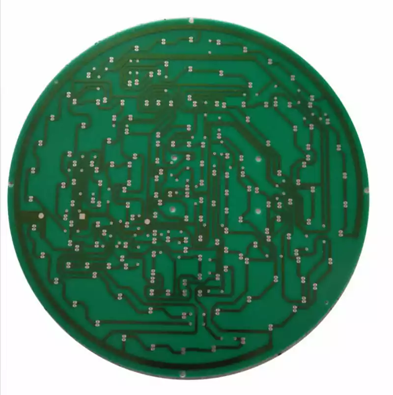
When selecting suitable laminates, the following key factors must be prioritized:
- Processing and Manufacturing Performance:
Includes multiple lamination characteristics, temperature adaptability, resistance to CAF (conductive anode filament) and heat resistance, mechanical toughness and adhesion (ensuring high reliability), and fire safety ratings. - Product-specific performance characteristics (including electrical properties and stability):
Materials should exhibit low signal loss, stable Dk (dielectric constant)/Df (dielectric loss factor) parameters, low dispersion characteristics, minimal frequency/environmental variation coefficients, and precise tolerances for material thickness and adhesive content (enabling accurate impedance control). For extended trace lengths, low-roughness copper foil is recommended. Additionally, high-speed circuit design relies heavily on simulation during the initial phase, with simulation results providing critical design guidance. The “Xingsen Technology-Agilent (High-Speed/RF) Joint Laboratory” has effectively addressed the industry challenge of simulation-measurement discrepancies. Through extensive closed-loop verification of simulations and actual measurements, it has achieved high alignment between simulation and test results using unique methodologies. - Timeliness of Material Supply:
Procurement cycles for many high frequency pcb laminates can be lengthy, reaching 2 to 3 months. While standard laminates like RO4350 are stocked, most require customer-supplied materials. Therefore, advance communication with suppliers is essential to ensure timely material preparation for high-frequency laminates. - Cost Considerations:
Decisions must be made based on the product’s price sensitivity, clarifying whether it targets the consumer market or applications in communications, medical, industrial, military, or other sectors. - Compliance Requirements:
Ensure materials meet environmental regulations across different countries, such as RoHS (Restriction of Hazardous Substances) and halogen-free standards.
The performance of high frequency PCB is influenced by multiple factors including material selection, processing, and cost. Only through comprehensive evaluation and the right material choice can high-quality high frequency PCB be produced, injecting robust momentum into the advancement of high-frequency technology.
