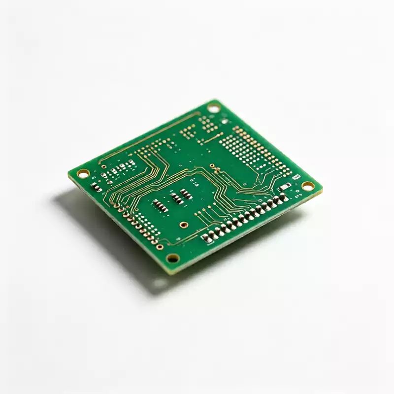
FR4 is the default substrate for most PCBs, and whether it can support high speed signals comes down to two electrical parameters: the dielectric constant (Dk) and the dissipation factor (Df) of FR4. Dk sets how fast a signal travels through the dielectric, and Df sets how much of its energy turns into heat. Both values move with frequency and temperature, and at GHz rates the high speed behavior of FR4 is governed by exactly these two numbers.
Typical values of the FR4 dielectric constant
Standard FR4 carries a Dk rating of 4.2 to 4.8 measured at 1 GHz, and most designs use 4.4 to 4.5 for rough estimates. The number is not fixed, because FR4 is a mix of glass cloth and epoxy resin: glass fiber sits near Dk 6 while the resin is about 3.2, so the blend ratio decides the final Dk. Frequency pulls it down as well. A laminate reading 4.5 at 1 GHz often falls to around 4.0 by 10 GHz. Different suppliers and different glass styles (1080, 2116, 7628) post different Dk values too. A serious design should not lean on a single textbook number; it should use the measured Dk-Df curve for the actual part number.
How the FR4 dielectric constant sets signal speed and delay
Signal velocity in the laminate is v = c / √Dk, so a larger Dk means slower propagation. With FR4 Dk around 4.2 to 4.5, signals move at roughly half the speed of light in vacuum. That shows up directly as delay: about 140 ps per inch on a surface trace and about 166 ps per inch on an inner layer where the reference plane is farther away. In tight-timing links like DDR5, a few inches of trace delay can exhaust the entire timing budget. Dk also fixes characteristic impedance. When batch Dk drifts by ±5%, a 75Ω trace can land anywhere from 71 to 79Ω, right at the edge of the matching window.
How the FR4 dissipation factor attenuates high speed signals
Df describes the share of signal energy the dielectric converts to heat. FR4 Df runs about 0.015 to 0.025 at 1 GHz. Dissipation loss scales roughly with frequency, so the higher you go, the harder Df hits. At 10 GHz, standard FR4 dielectric loss measures around 0.4 dB per inch, while Rogers RO4350B sits near 0.25 dB per inch. A 100 mm FR4 trace at 10 GHz can lose more than 3 dB extra, which is about half the signal power. The result is a compressed rising edge and a collapsed eye diagram, and high speed differential links fail training. That is why a 1 Gbps link stays clean while 56G PAM4 keeps throwing errors.
Effects of FR4 dielectric constant drift with frequency and temperature
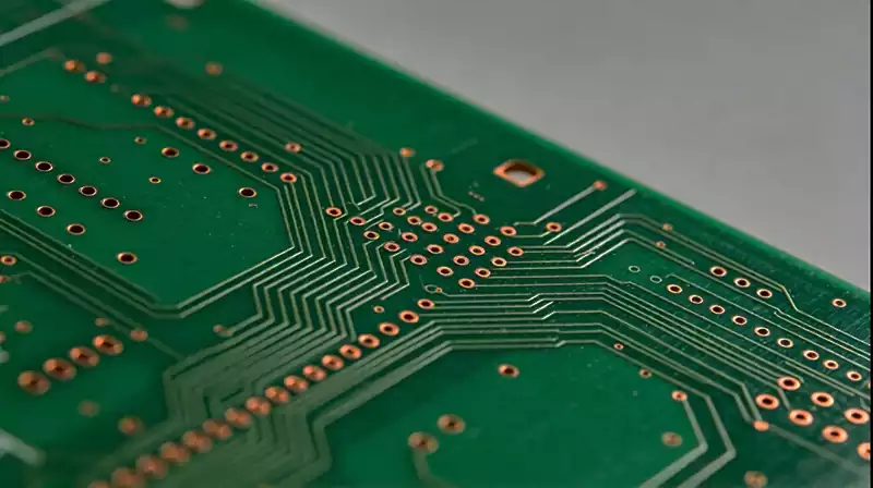
Beyond the absolute value, FR4 Dk and Df are not stable. Dk falling with frequency means different frequency components travel at different speeds, which produces intersymbol interference and edge distortion. Temperature makes the shift worse. At 85°C board temperature, FR4 Dk rises about 0.12 and Df climbs about 40%, while premium materials barely move. The glass weave effect is another factor that gets missed. Glass bundles and resin gaps have different Dk, glass about 6 and resin about 3.2, so a trace crossing weave regions sees local impedance discontinuities that inject jitter and phase noise into 28 Gbps and faster differential pairs.
When to switch materials based on FR4 Dk and Df
In practice, once links pass 3 to 5 GHz or run at multi-Gbps rates, FR4 Df and Dk stability start falling short. Sorting by data rate is clearer. Laminates with Df between 0.01 and 0.005 carry up to 10 Gb/s, 0.005 to 0.003 reach 25 Gb/s, and 50 Gb/s and above need Df no higher than 0.0015. Rogers RO4350B, Dk 3.48 and Df 0.0037, Panasonic Megtron 6, Dk 3.49 and Df 0.0017, and Megtron 7, Dk 3.30 and Df 0.0013, are common upgrades. Millimeter-wave work at higher frequencies calls for PTFE, RT/duroid 5880, Dk 2.20 and Df 0.0009. Note that high-Tg FR4 only raises heat resistance. The resin system is unchanged, so its 10 GHz Df stays at 0.015 to 0.021 and the signal integrity problem remains.
Common questions engineers ask about FR4 dielectric constant
What Dk value should I use for impedance calculation? For low speed boards, 4.5 to 4.7 is fine. For high speed work, do not reuse a textbook number. Pull the measured Dk at the target frequency from the laminate datasheet, and at higher frequencies design conservatively around the lower 4.2 to 4.3.
Can high speed boards still use FR4? Below 3 GHz with short traces, FR4 meets the requirement, and Bluetooth or industrial IoT links gain cost advantage from it. Once you enter 5G Sub-6, PCIe 5.0 and above, or millimeter wave, you need a low-Df, stable-Dk material instead.
Does halogen-free FR4 hurt dielectric performance? Yes. Halogen-free formulations swap in phosphorus flame retardants, which widen Dk spread to about ±0.3 and typically add 0.003 to 0.005 of Df degradation. Stack-up simulations need to budget for that variation.
FR4 holds roughly 85% of the low and mid speed market because it is economical and reliable in ordinary circuits. But in high speed designs, whether the board works at all basically depends on the stability of the FR4 dielectric constant and the size of its Df. Start a high speed layout by fixing the operating frequency and the loss budget. The laminate maker can supply the Dk-Df curve for your simulation, leave ±5% impedance margin, and verify critical links with TDR. Controlling these parameters usually beats jumping straight to a more expensive laminate.