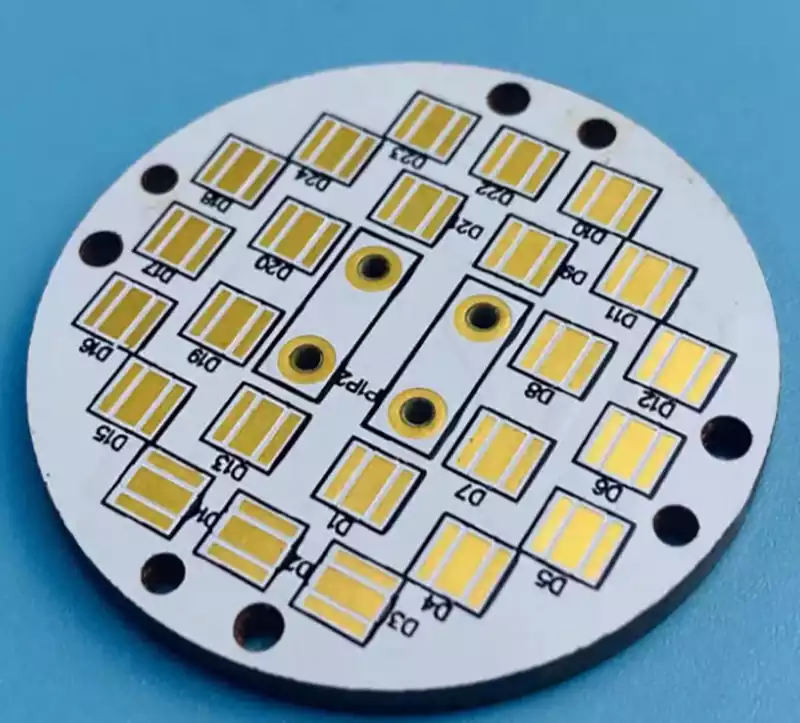
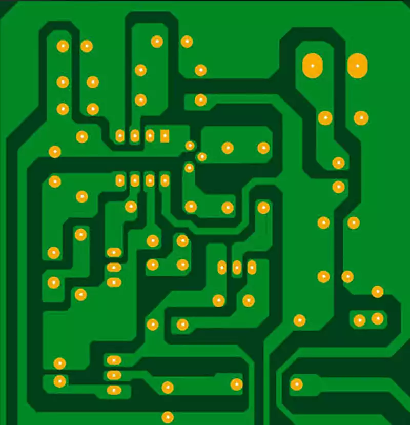
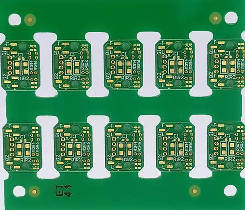
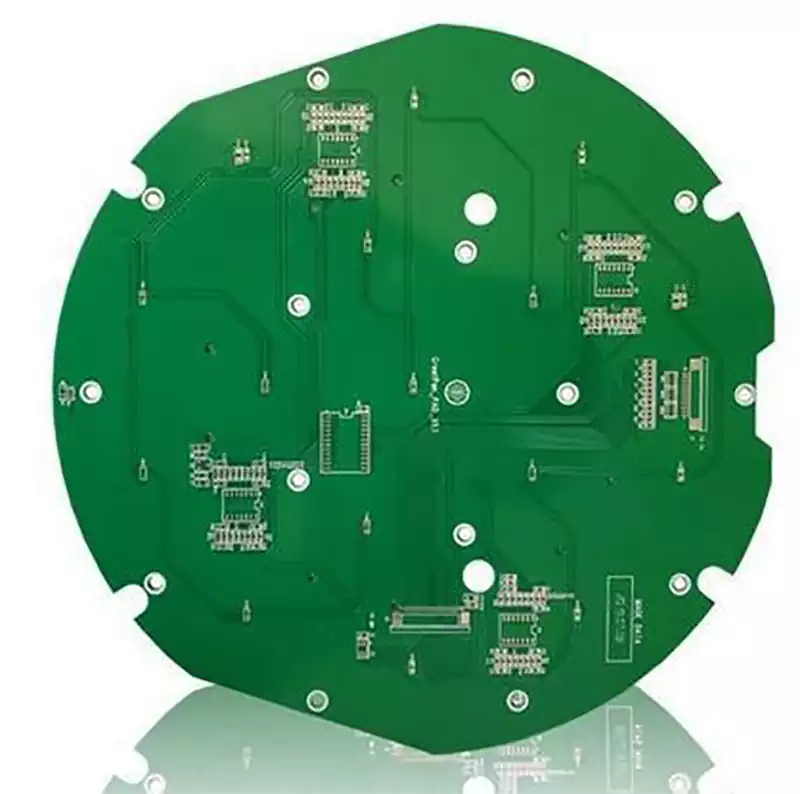
FR4 ranks as the most widely adopted copper clad laminate substrate in the field of printed circuit board manufacturing. Many practitioners simply define it as glass fiber reinforced epoxy sheet, yet from the perspective of industrial standards, FR4 essentially refers to a flame retardant specification formulated by the National Electrical Manufacturers Association (NEMA) of the United States.
FR is the abbreviation for Flame-Retardant, and the exclusive definition of FR4 reads as a dedicated substrate for circuit boards that adopts epoxy resin as the matrix resin and electronic-grade glass fiber cloth as the reinforcing base material, while meeting the UL94 V-0 flame retardant standard.
Currently, commercially available FR4 sheets on the market mainly adopt tetrafunctional epoxy resin as the core raw material, compounded and pressed with special filler additives and high-quality electronic glass fiber cloth, which can adapt to the vast majority of conventional PCB manufacturing and application scenarios. The PCB industry boasts a full range of substrate types with distinct differences in structure, composition and flame retardant performance. The classified parameters of each substrate type are shown in the table below:
| Substrate Material Type | Industry Grade Code | Core Raw Material Composition | Flame Retardant Standard |
|---|---|---|---|
| Paper-based substrate | XPC | Phenolic resin + wood pulp fiber paper | Non-flame retardant, compliant with UL94 HB |
| Paper-based substrate | XXPC | Modified phenolic resin + wood pulp fiber paper | Non-flame retardant, compliant with UL94 HB |
| Paper-based substrate | FR-1 | Flame retardant phenolic resin + wood pulp fiber paper | Flame retardant, compliant with UL94 V-1 |
| Paper-based substrate | FR-2 | Flame retardant phenolic resin + wood pulp fiber paper | Flame retardant, compliant with UL94 V-1 |
| Glass cloth-based substrate | FR-4 | Epoxy resin + electronic-grade glass cloth | Flame retardant, compliant with UL94 V-0 |
| Glass cloth-based substrate | FR-5 | Epoxy resin + electronic-grade glass cloth | Flame retardant, compliant with UL94 V-0 |
| Composite substrate | CEM-1 | Epoxy resin + fiber paper + glass cloth | Flame retardant, compliant with UL94 V-0 |
| Composite substrate | CEM-3 | Epoxy resin + glass cloth + glass mat | Flame retardant, compliant with UL94 V-0 |
Characteristics and Application Scenarios of Various PCB Substrates
1.Paper-based Substrates
This category of substrates takes wood pulp fiber paper as the core reinforcing layer, laminated and molded with phenolic resin as adhesive. XPC and XXPC feature no flame retardant capability, while FR-1, FR-2 and FR-3 are modified to achieve flame retardancy. The biggest advantage of paper-based substrates lies in high cost performance and low production costs, yet they suffer inferior mechanical properties and heat resistance. They are only applied to low-end electronic products with low performance requirements, such as toys, simple household appliances, calculators and landline telephones.
2.Glass Cloth-based Substrates
Also known as epoxy sheets or glass fiber sheets, they serve as core substrates for mid-to-high end PCBs, covering FR4 and FR5 products. Adopting electronic-grade glass fiber cloth as the reinforcing material and epoxy resin as the bonding medium, they deliver high overall mechanical strength, outstanding heat resistance and stable dielectric properties. Benefiting from balanced comprehensive performance, glass cloth-based substrates have become the most widely consumed PCB substrates with the broadest applicable scenarios, extensively utilized in core sectors including mobile communication equipment, smart televisions, high-end consumer electronics and industrial control devices.
3.Composite Substrates
CEM-1 and CEM-3 represent mainstream commercial grades, with performance and cost positioned between paper-based substrates and pure glass fiber substrates, acting as cost-effective transitional base materials. CEM-3 offers electrical performance comparable to standard FR4 sheets and superior drillability. Meanwhile, it outperforms ordinary economical FR4 sheets in multiple indicators such as dimensional stability, comparative tracking index and dimensional precision, and is widely adopted for mid-range electronic products requiring moderate machining precision without high-frequency performance demands.
Core Performance Parameters and Selection Criteria of FR4 Sheets
The service performance and applicable scenarios of FR4 sheets are determined by multiple core indicators, including glass transition temperature (Tg), thermal decomposition temperature (Td), dielectric constant (Dk), dissipation factor (Df), comparative tracking index (CTI), coefficient of thermal expansion (CTE), water absorption and peel strength of copper foil. To intuitively reflect performance gaps among mainstream products, benchmark FR4 materials from three globally renowned manufacturers Isola, Nelco and Ventec are compared in the parameter table below:
| Performance Parameter | Isola 370HR | Nelco N4000-13 | Ventec VT-47 |
|---|---|---|---|
| Glass Transition Temperature Tg (℃) | 180 | 210 | 170 |
| Thermal Decomposition Temperature Td (℃) | 340 | 350 | 340 |
| Dielectric Constant Dk at 10GHz | 3.92 | 3.60 | 4.27 |
| Dissipation Factor Df at 10GHz | 0.025 | 0.009 | 0.046 |
| CTI Performance PLC Grade | 3 | 3 | 3 |
| Water Absorption Rate (%) | 0.15 | 0.10 | 0.12 |
1.Core Heat Resistance Indicators: Tg and Td
Glass transition temperature Tg refers to the critical temperature at which the physical form of the substrate undergoes qualitative changes. When the ambient temperature stays below Tg, the sheet maintains rigid and stable glassy state; once the temperature exceeds Tg, the substrate softens with increased elasticity and becomes prone to deformation. This transition is reversible, and the sheet can recover its original rigidity after cooling down. Thermal decomposition temperature Td stands for the ultimate heat resistance threshold of the substrate. Temperatures exceeding Td will trigger irreversible thermal decomposition of internal resin, causing permanent damage and complete loss of service performance.
Based on Tg values, the industry categorizes FR4 sheets into three grades: low Tg sheets (around 135℃), mid Tg sheets (around 150℃) and high Tg sheets (170℃ and above). High Tg FR4 sheets are mandatory for high thermal stress working conditions such as lamination of high-layer count PCBs, wave soldering, peak soldering temperature over 230℃ and long-term equipment operation under ambient temperature above 100℃, to avoid substrate deformation and delamination failure.
2.High-frequency Electrical Indicators: Dk and Df
Dielectric constant Dk and dissipation factor Df are core parameters governing the high-frequency signal transmission performance of substrates, and both values fluctuate with the frequency of operating signals. Df reflects the level of signal transmission loss; higher Df values lead to more severe signal attenuation and distortion. Dk directly affects the impedance stability of PCB traces, serving as a core reference for high-precision impedance design. The industry classifies FR4 sheets into four loss grades based on Df values:
| Loss Grade | Dissipation Factor Df Range |
|---|---|
| Standard Loss Grade | Df ≥ 0.02 |
| Medium Loss Grade | 0.01 ≤ Df < 0.02 |
| Low Loss Grade | 0.005 ≤ Df < 0.01 |
| Ultra-Low Loss Grade | Df < 0.005 |
3.Insulation Safety Indicator: CTI Comparative Tracking Index
The comparative tracking index (CTI) evaluates the ability of insulating substrates to resist high voltage tracking breakdown. During PCB operation, carbonized conductive paths may form on the insulation surface due to high temperature or moisture, triggering electrode short circuits and equipment failures. Higher CTI values indicate stronger insulation breakdown resistance of the substrate, which can effectively reduce the required creepage distance between PCB conductors. The industry divides PLC performance grades according to CTI voltage ranges; smaller grade numbers correspond to superior insulation performance:
| CTI Test Voltage Range | PLC Performance Grade |
|---|---|
| ≥600V | 0 |
| 400V ~ 600V (exclusive of 600V) | 1 |
| 250V ~ 400V (exclusive of 400V) | 2 |
| 175V ~ 250V (exclusive of 250V) | 3 |
| 100V ~ 175V (exclusive of 175V) | 4 |
| <100V | 5 |
High CTI grade FR4 sheets must be adopted for scenarios with strict insulation safety requirements including aerospace, marine equipment and high-voltage power equipment to guarantee long-term stable equipment operation.
Application Limitations of FR4 Sheets
Boasting core strengths including high cost performance, broad machining compatibility, stable electrical performance, sufficient mechanical strength and satisfactory conventional heat resistance, FR4 has become the preferred substrate for general-purpose PCBs. Nevertheless, FR4 presents prominent performance drawbacks that fail to meet the design requirements of high-end products in high-frequency high-speed signal transmission, high-power heat dissipation, ultra-precision manufacturing and other premium application scenarios, with specific limitations listed as follows:
Excessive transmission loss for high-frequency signals
With the rising signal transmission speed and lengthened PCB trace lengths of electronic products, the signal loss defect of standard FR4 sheets becomes increasingly prominent. Standard FR4 features a Df value of approximately 0.020, while dedicated high-speed high-frequency substrates can reach a Df as low as 0.004, delivering merely one quarter of FR4’s transmission loss. Meanwhile, the dielectric loss of FR4 rises exponentially with signal frequency, aggravating signal attenuation and distortion, whereas specialized high-frequency materials show mild loss growth and superior stability under high-frequency working conditions. Therefore, high-speed PCB design requires matching dedicated low-loss substrates corresponding to operating frequencies instead of relying on standard FR4 sheets.
Low precision of impedance control
The impedance value of PCB traces is directly determined by the substrate’s Dk value. Unstable and discontinuous impedance will trigger signal integrity faults such as signal overshoot, reflection and ringing. Standard FR4 sheets carry a maximum dielectric constant error up to 10% with wide value fluctuation ranges, while premium high-frequency substrates can control Dk error within 2%, delivering far superior impedance precision compared to FR4. Restricted by this precision defect, FR4 cannot be applied to high-speed and high-frequency electronic products requiring high-precision impedance matching design.
Poor thermal conductivity and heat dissipation capacity
FR4 sheets only achieve a thermal conductivity coefficient of 0.3~0.4 W/m·K, featuring extremely low thermal conductivity and poor heat dissipation performance. For high-power power supplies and high-frequency power devices with massive heat generation, relying solely on FR4 substrates cannot timely dissipate operational heat, easily causing heat accumulation and excessive temperature rise, which impairs service life and operational stability. For high-power products, the industry commonly adopts high thermal conductivity substrates, embedded copper pillars/copper blocks, metal core PCBs and other solutions to compensate for FR4’s insufficient heat dissipation capacity.
Poor dimensional stability under high-temperature environments
FR4 sheets tend to warp, deform and shift in dimensions under long-term high-temperature working conditions. The peak temperature of lead-free reflow soldering can reach 250℃, exceeding the Tg critical temperature of most standard FR4 sheets. Thermal expansion stress generates after substrate heating and remains residual after cooling, readily inducing quality defects such as component cold solder joints, cracked solder joints and board deformation. Industrial practice proves that premium substrates with low coefficient of thermal expansion (CTE) should be prioritized for PCBs mounted with components larger than 3.2×1.6mm to avoid quality risks brought by high-temperature deformation.