Printed circuit board materials influence how a board handles electrical signals, heat, mechanical stress and the manufacturing process. A substrate that works well for a standard control board may not be the right choice for a high-speed networking device, an RF circuit or a product exposed to repeated thermal cycling. Material selection therefore needs to reflect the conditions in which the finished board will operate.
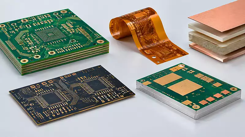
FR-4 remains a common choice for rigid printed circuit boards because it offers a practical balance of electrical insulation, mechanical strength, processability and cost. Other designs may require high Tg laminates, low loss materials, flexible polyimide films or metal-core constructions. Each option has its own characteristics, and the most suitable material depends on the complete board design rather than a single specification.
For engineers and procurement teams, understanding these differences makes it easier to define a PCB stackup, compare fabrication quotations and avoid material substitutions that could affect product performance.
What Are Printed Circuit Board Materials?
Printed circuit board materials include the insulating substrates, copper foils, bonding materials and protective layers used to build a PCB. In a rigid multilayer board, the main dielectric structure is generally formed from copper-clad laminate and prepreg. These materials are combined to create the required layer arrangement, board thickness and electrical insulation.
The substrate separates conductive layers and supports the copper circuitry. Copper foil forms traces, pads and reference planes, while prepreg provides the resin and reinforcement needed to bond layers during lamination. The completed structure must maintain suitable electrical, mechanical and thermal properties throughout fabrication, assembly and service.
Material specifications can cover several different properties. Glass transition temperature (Tg) describes a change in the behavior of the resin system as temperature rises.
Decomposition temperature (Td) measures thermal degradation under a defined test method. Dielectric constant (Dk) and dissipation factor (Df) help characterize electrical behavior, particularly in high-speed and high-frequency applications. Coefficient of thermal expansion (CTE), moisture absorption and thermal conductivity can also matter, depending on the board’s construction and operating environment.
These properties should be evaluated together. A higher Tg, for example, does not automatically mean that a laminate has lower signal loss or better thermal conductivity. Material selection works best when each specification is tied to a real design requirement.
Common Types of Printed Circuit Board Materials
Different laminate families are developed to meet different combinations of electrical, thermal and mechanical requirements. The following materials are widely used across rigid, flexible and specialized PCB designs.
FR-4 PCB Material
FR-4 is a glass-fiber-reinforced epoxy laminate commonly used in rigid printed circuit boards. The glass reinforcement provides structural support, while the epoxy resin bonds the material and provides electrical insulation. Its established fabrication processes and broad availability make FR-4 suitable for many commercial and industrial electronic products.
Applications include control boards, consumer electronics, instrumentation and a wide range of multilayer designs. Standard FR-4 can be suitable where the circuit’s electrical performance, thermal exposure and reliability requirements fall within the selected grade’s capabilities.
The term FR-4 covers a family of materials rather than one universal formulation. Different grades can have different Tg values, dielectric properties, moisture behavior and thermal reliability characteristics. Two laminates labeled FR-4 should not automatically be treated as interchangeable when the design has tightly controlled electrical or thermal requirements.
When specifying FR-4, the design team should identify the required material grade or the relevant performance criteria. For demanding multilayer boards, the choice should also account for layer count, copper weights, board thickness and the assembly’s soldering profile.
High-Tg FR-4
High-Tg FR-4 is designed for applications that need greater thermal stability than a standard-grade laminate can provide. During lead-free assembly, a PCB may experience elevated temperatures over multiple reflow cycles. A suitable high-Tg material can help the board maintain its structural and dimensional stability under these conditions.
High-Tg laminates may be considered for multilayer boards, industrial electronics, telecommunications equipment and other products with demanding assembly or operating requirements. However, Tg alone is not a complete measure of thermal reliability. Decomposition temperature, Z-axis expansion, moisture behavior and the material’s compatibility with the overall fabrication process also deserve attention.
The right grade should be selected against the actual thermal profile and reliability targets. Choosing the highest available Tg without considering other properties may add cost without delivering a meaningful benefit.
High-Frequency and Low-Loss PCB Materials
High-frequency PCB materials are used when signal loss, dielectric consistency and impedance control become important design constraints. Depending on the application, suitable material systems may include PTFE-based laminates, ceramic-filled materials or specialized low-loss epoxy laminates.
The dielectric constant affects how electromagnetic fields propagate through the board, while the dissipation factor indicates dielectric energy loss under specified measurement conditions. These properties influence signal propagation and attenuation, particularly in RF, microwave and high-speed digital circuits.
FR-4 can still be suitable for some high-frequency designs, depending on the operating frequency, signal path length, loss budget and selected laminate grade. As requirements become more demanding, a lower-loss material may be needed. The decision should be based on the electrical design rather than frequency alone.
Designers also need to consider copper surface roughness, dielectric thickness, impedance tolerances and the reference-plane arrangement. Even a suitable laminate cannot compensate for a poorly designed transmission line or an inconsistent stackup.
Polyimide PCB Materials
Polyimide is commonly used in flexible printed circuit boards and selected high-temperature applications. Its film-based construction allows circuits to bend and fit into compact spaces where a rigid FR-4 board would be impractical. Polyimide is also used in some rigid-flex constructions, where flexible sections connect rigid regions of the same circuit assembly.
Material selection for a flex circuit must account for the intended bend radius, number of flex cycles, copper type and thickness, adhesive system where applicable, and the location of vias and components. A board designed for occasional installation bending may use a different construction from one that flexes repeatedly during operation.
Polyimide materials also have distinct thermal and electrical characteristics. The specific grade and complete flex stackup should be evaluated for the product’s requirements rather than assuming that all polyimide constructions behave identically.
Metal-Core PCB Materials
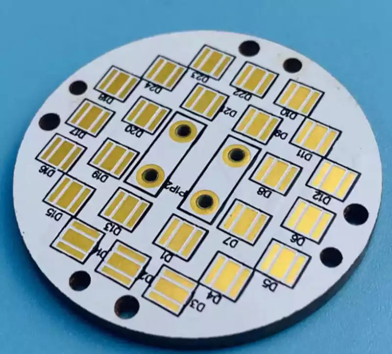
Metal-core PCBs use a metal base, commonly aluminum or copper, together with an electrically insulating dielectric layer and a conductive circuit layer. The metal base helps transfer heat away from heat-generating components, making this construction useful in applications such as LED lighting and selected power electronics.
The thermal performance of a metal-core board depends on more than the metal base itself. Dielectric thermal conductivity and thickness, copper layout, component placement, mounting conditions and the external heat sink all contribute to the final thermal path.
Metal-core construction also differs from a conventional multilayer FR-4 stackup. The material structure and routing options should be confirmed during design, particularly when the circuit has isolation requirements, high current or mechanical mounting constraints.
Other Specialized Substrates
Some applications call for ceramic substrates, low-loss resin systems or hybrid constructions that combine different dielectric materials in one board. Ceramic materials can be appropriate for specialized thermal, electrical or packaging requirements. Hybrid PCB stackups can combine conventional and high-frequency laminates when different sections of a circuit have different performance needs.
These solutions require closer coordination between design and fabrication. Material compatibility, lamination conditions, thermal expansion and the transition between different dielectric systems need to be assessed before the stackup is finalized.
Comparison of Common Printed Circuit Board Materials
The table below provides a qualitative comparison. Actual performance depends on the specific laminate grade, stackup, test method and manufacturing construction.
| Material | Main characteristics | Typical applications | Main considerations |
|---|---|---|---|
| Standard FR-4 | General-purpose rigid laminate with broad availability | Commercial electronics, control boards, many multilayer PCBs | Confirm grade, thermal profile and electrical requirements |
| High-Tg FR-4 | Improved thermal stability for demanding fabrication or assembly conditions | Multilayer boards, industrial and telecommunications electronics | Tg is only one part of thermal reliability |
| Low-loss laminate | Designed to reduce dielectric loss and support controlled electrical performance | High-speed digital, RF and microwave circuits | Compare Dk and Df at relevant frequencies and test conditions |
| Polyimide | Flexible film construction with useful thermal characteristics | Flexible and rigid-flex PCBs | Bend life, copper construction and flex geometry |
| Metal-core laminate | Metal base supports heat transfer through the board structure | LED lighting and selected power electronics | Dielectric thermal resistance and overall heat-sink design |
| Ceramic substrate | Specialized electrical and thermal properties, depending on ceramic composition | Selected power, RF and high-reliability applications | Material-specific processing, design constraints and cost |
A comparison table is useful for narrowing the options, but the final selection should be made using manufacturer datasheets and the complete PCB specification. Published Dk and Df values, for example, are meaningful only when their measurement frequency and method are understood.
Key Factors in PCB Material Selection
Selecting a PCB material requires the electrical, thermal and mechanical demands of the product to be considered together.
Electrical Performance and Signal Integrity
For high-speed and RF circuits, the dielectric properties of the laminate influence impedance, propagation delay and signal attenuation. Dk is relevant to transmission-line design, while Df helps characterize dielectric loss. The consistency of these values across the operating frequency and temperature range can also matter.
The material must be evaluated alongside trace geometry, copper roughness, dielectric thickness and reference-plane placement. Where impedance control is required, the fabricator should receive the target impedance and the associated stackup constraints so the construction can be reviewed before production.
Thermal Requirements
PCB materials experience heat during both assembly and operation. The selected laminate needs to tolerate the expected processing conditions, while the finished board must remain suitable for its intended service environment.
Tg, Td, CTE and thermal conductivity describe different aspects of material behavior. Tg relates to the transition in resin behavior, Td concerns decomposition, CTE describes dimensional expansion with temperature, and thermal conductivity indicates how readily heat moves through the material. These values should not be used interchangeably.
For products with substantial heat generation or repeated temperature changes, the design team should review the full thermal path and the expected stress on plated holes, solder joints and the board structure.
Mechanical Strength and Flexibility
A rigid board must maintain its dimensions and support its components through handling, assembly and operation. Flexible designs have additional requirements because the circuit may bend around an enclosure or move repeatedly during use.
The material choice should match the intended mechanical loading. Board thickness, reinforcement, copper construction, mounting points and local geometry can influence the result just as much as the base dielectric.
Moisture and Environmental Exposure
Moisture absorption can affect some electrical and mechanical properties and may influence reliability during thermal processing. Operating temperature, humidity, chemical exposure and the expected service life should therefore be included in the material review when they are relevant to the product.
Environmental requirements may also affect the selection of resin system, surface finish and protective coatings. These factors should be defined before fabrication rather than left to assumptions about a generic material family.
Manufacturing Compatibility
A material must be suitable for the fabrication process used to produce the specified board. Lamination, drilling, desmear, plating and dimensional registration can be affected by the selected material system and board construction. Specialized laminates may also require different processing controls from standard FR-4.
For mixed-material or hybrid designs, the fabricator should review the proposed stackup before the design is released. Confirming material availability, compatible prepreg, layer bonding and the required tolerances can reduce engineering changes later in production.
Cost and Availability
Material cost is only one part of the total PCB cost. Availability, minimum order quantities, fabrication complexity, scrap risk and lead time can also influence the final quotation. A specialized laminate may be justified by a strict electrical or thermal requirement, while a standard FR-4 grade may meet the needs of a less demanding circuit.
Procurement teams should compare quotations using equivalent specifications. If two quotations use different laminate grades or stackups, a lower price does not necessarily represent an equivalent product.
How PCB Materials Affect Multilayer Stackup Design
Material selection and stackup design should be developed together. In a multilayer PCB, the stackup defines the arrangement of copper layers, dielectric cores and prepreg. The selected materials and their thicknesses influence the board’s finished thickness, impedance, mechanical stability and lamination requirements.
For controlled-impedance designs, the dielectric thickness and Dk are part of the transmission-line calculation. Copper weight and trace geometry also influence the resulting impedance. A change in laminate grade or dielectric thickness can therefore require the routing geometry to be reviewed.
Thermal expansion is another important consideration. Different materials and copper structures expand at different rates when heated. In multilayer boards, this behavior can influence registration and the stresses placed on plated through-holes during thermal cycling.
The stackup should be confirmed with the PCB fabricator before production when the design has strict impedance targets, specialized laminates, unusual thickness requirements or mixed-material construction. This review helps ensure that the material specification can be translated into a manufacturable board.
What Information Should Be Included in a PCB Material Specification?
A clear material specification helps the fabricator understand the intended construction and prevents different assumptions from being used during quotation and production.
The documentation should identify the required laminate family or approved material grade, finished board thickness, copper weights, layer count and stackup. For high-speed or RF designs, it should also include impedance requirements and the relevant electrical parameters. Thermal and mechanical requirements should be documented where they affect the material choice.
If an exact manufacturer and grade are mandatory, state that requirement clearly. If equivalent materials are acceptable, define the performance criteria that an alternative must meet and require approval before substitution. This is particularly important when the design depends on specific dielectric properties or thermal behavior.
For flexible, metal-core or hybrid boards, include the construction details needed to evaluate the specialized material system. The RFQ should also identify the expected quantity and any testing or certification requirements relevant to the product.
Frequently Asked Questions About Printed Circuit Board Materials
What is the most commonly used PCB material?
FR-4 is widely used for rigid printed circuit boards because it provides a practical balance of mechanical strength, electrical insulation, processability and cost. The appropriate grade depends on the board’s thermal, electrical and reliability requirements.
Is FR-4 suitable for high frequency PCBs?
FR-4 can be suitable for some high-frequency designs, but the decision depends on the selected grade, operating frequency, signal path length and loss budget. More demanding applications may require a low-loss laminate with better-controlled dielectric properties.
What is the difference between standard FR-4 and high-Tg FR-4?
Both are glass-fiber-reinforced epoxy laminate systems, but high-Tg grades are designed for greater thermal stability. The right choice depends on the assembly profile and reliability requirements. Tg should be evaluated alongside decomposition temperature, CTE and other relevant properties.
Which material is used for flexible PCBs?
Polyimide is widely used for flexible circuits because it is available in thin film constructions that can bend to fit the product. The complete flex construction, including copper and bonding layers, must be selected according to the required bend radius and flex life.
What PCB material is best for heat dissipation?
There is no single best material for every thermal application. Metal core PCBs can help transfer heat away from components, while other designs may use specialized dielectric materials or thermal structures. The complete path from the component through the board and into the heat sink determines the result.
Can different PCB materials be combined in one board?
Yes. Some designs use hybrid stackups that combine different laminate systems to meet electrical and mechanical requirements in different parts of the circuit. Such designs require careful review of material compatibility, lamination and thermal expansion.
Printed circuit board materials affect electrical behavior, thermal reliability, mechanical strength and fabrication requirements. FR-4 remains a practical choice for many rigid boards, while high-Tg laminates, low-loss materials, polyimide, metal-core constructions and specialized substrates address more specific needs.
The best printed circuit board material is the one that satisfies the product’s actual requirements and can be manufactured consistently within the project budget and schedule. By defining the electrical targets, thermal conditions, mechanical constraints and stackup requirements early, design and procurement teams can make better-informed decisions and reduce avoidable changes during fabrication.