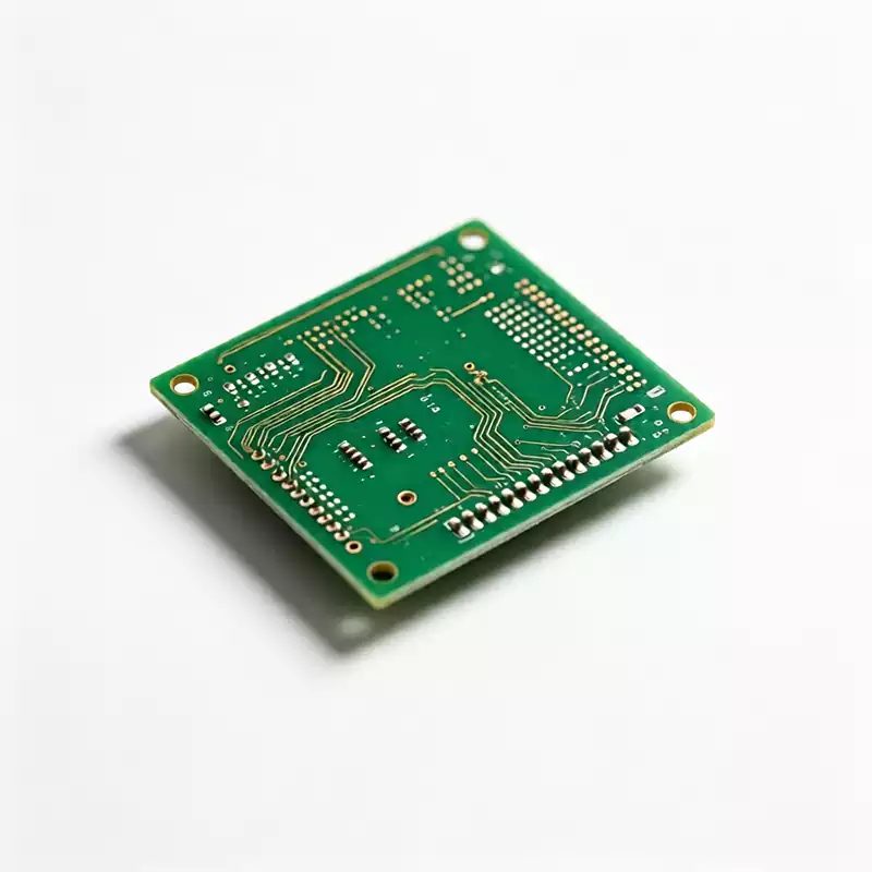
What is an automotive PCB? In plain terms, it is the circuit board inside your car. A smart electric vehicle carries 80 to 150 of them, from the instrument cluster to the traction inverter.
What materials do automotive PCBs use? FR-4, high-Tg laminates, polyimide, Rogers-grade high-frequency boards, aluminum and copper base boards, ceramic substrates. Count them on your fingers and you run out well past a dozen.
But why do automotive PCBs need high-performance, high-spec materials at all? The “good enough” logic that governs consumer electronics stops working the moment a board goes into a vehicle.
Three numbers explain why: 150°C, 15 years, and 50 ppm. PCB Boards in the engine bay live above 150°C for years. Vehicle design life is reckoned in 15-year terms. And the failure rate target is 50 parts per million or lower. This is not a market where good enough wins. It is a market where failure is not an option, and automotive PCB materials are where that option gets taken away.
What makes automotive PCB materials different
Plenty of engineers meet their first automotive program assuming a PCB is a PCB board. Consumer electronics has used them for decades, so what could possibly go wrong? Quite a lot, actually.
Start with temperature. Engine control units, transmission modules, and motor controllers sit against heat that never really lets up, above 150°C for the life of the vehicle. The complication is that every board also passes through a lead-free reflow oven on the way out of the factory, with peak temperatures of 245 to 260°C. Standard FR-4 has a glass transition temperature of only 130 to 140°C. At reflow peaks the resin softens, the Z-axis expands sharply, and the plated barrel of every metalized hole is the first thing to tear. A whole oven of delaminated boards is not a rare story on production lines.
Then there is vibration. Hard braking and rough roads put 20G of acceleration and 10 to 2000 Hz of random vibration into the chassis, and solder joints and via barrels have to survive that for a decade and more. Thick-copper process lines have a number for this: hold barrel copper at 225 μm or more, and resistance shifts by less than 3% after a million vibration cycles. Miss that margin, and the bill arrives years later as a warranty line item.
Now add it all up. Fifteen years of design life, a 50 ppm failure target, and every small defect becomes a potential safety incident. It might be a hidden CAF growth path, or just a bit of moisture absorption drifting the dielectric performance. A consumer board gets replaced in two years; an automotive PCB lives the entire vehicle lifecycle. The material logic is simply not the same.
The five automotive PCB material specs that matter
Every supplier with real automotive history keeps a laminate control document, and the same five numbers appear in all of them. Thresholds go straight into the standard file and get enforced.
| Spec | Automotive threshold | What happens below it |
|---|---|---|
| Glass transition temperature (Tg) | ≥170°C, ≥180°C for high-end | Delamination in reflow, cracked barrels |
| Decomposition temperature (Td) | ≥340°C | Resin breaks down at operating temperature |
| Z-axis CTE | ≤3% (25°C to 260°C) | Barrel copper torn apart by thermal cycling |
| CAF resistance | Pass 85°C / 85% RH with bias | Copper filaments grow, slow short circuits |
| Water absorption | <0.35% | Moisture raises dielectric loss, drops insulation |
Tg is the point where the resin crosses from glassy to rubbery. Past it, Z-axis expansion goes out of control, which is why automotive multilayer boards start at 170°C and high-end builds go to 180°C.
The spec people forget is Z-axis CTE. Copper expands at 17 ppm/°C. FR-4 resin runs about 50 ppm/°C below Tg, then jumps to 250 to 300 ppm/°C above it. A few thousand thermal cycles at that mismatch will tear a metalized hole apart. Getting Z-axis CTE under 3% takes three moves together: high Tg, high Td, and inorganic fillers.
CAF is the top risk wherever voltage is high. A battery pack always has some electrolyte vapor and condensation. Add heat, humidity, and DC bias, and copper ions grow conductive filaments along the glass bundles inside the laminate. Adjacent traces leak current slowly, then short. CAF resistance comes from dedicated resin formulations and spreadable glass cloth, and the material has to pass long-term testing at 85°C, 85% relative humidity, under strong electric field. High-voltage designs also watch CTI, the comparative tracking index, which should sit at 600V or above to keep surface arcing away when creepage distances get tight.
Matching automotive PCB materials to where the board sits
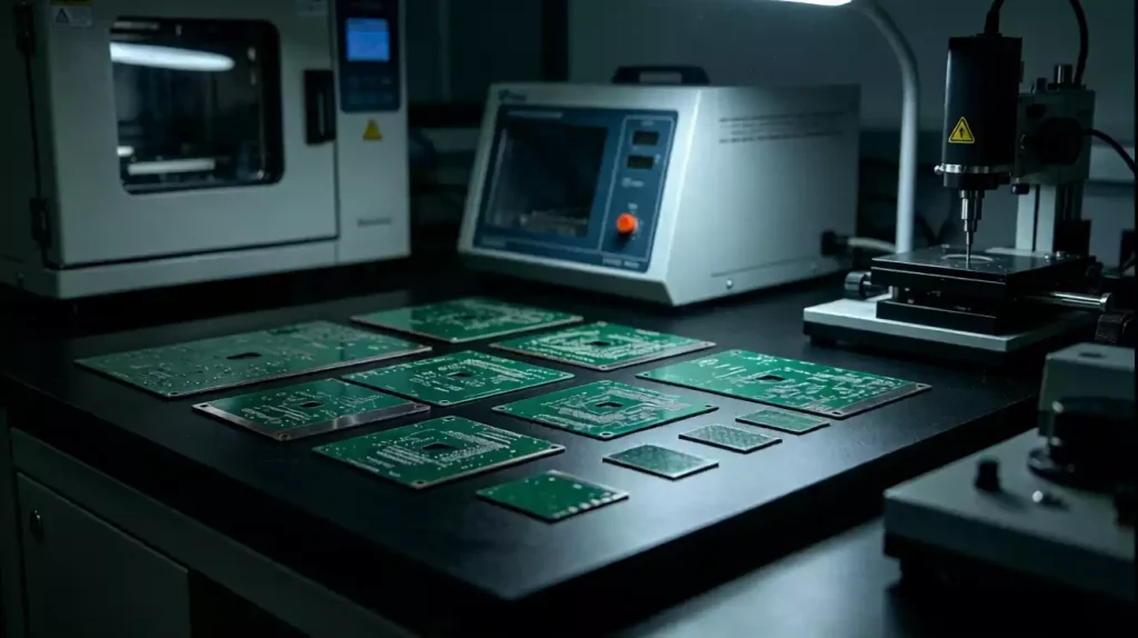
Cabin entertainment and body-control boards live in a mild environment and a cost-sensitive budget. Mid-high Tg FR-4 around 150°C with Td at 320°C or better and relaxed CTE is the normal answer. Boards with large copper areas or multiple reflow passes should still push Tg upward, mostly to keep warpage under control.
High-voltage boards inside the engine bay and battery pack, the BMS and traction inverter family, take the full spec with nothing relaxed: Tg≥170°C, Td≥340°C, Z-axis CTE≤3%, high CAF resistance, water absorption under 0.35%. The usual names here are Isola FR408HR, Shengyi S1000-2, and Taiyao TU-768. Two habits on these boards are worth more than any datasheet: lock the part number and the revision together into the BOM, and require IATF 16949 certification plus a secured long-term supply channel from the vendor. A single-source discontinuation can stop a production line faster than any material defect.
Millimeter-wave radar and automotive ethernet boards run high-speed signals, so they need low dielectric constant and low dissipation factor, with Dk tolerance held inside ±0.02. Rogers RO3000 and RO4000 series carbon-hydrocarbon ceramic laminates are common choices. One detail on these boards gets missed more than any other: the copper foil has to be RTF or HVLP. High-frequency current rides on the foil surface, roughness directly sets the loss, and a correct laminate paired with the wrong foil still wastes the money.
Thick copper, high frequency, and heat in automotive PCB materials
BMS main boards, motor drivers, and onboard chargers carry tens to hundreds of amperes, which makes thick copper foil standard. Foil thickness follows position: 1 oz (35 μm) on signal boards, 2 oz (70 μm) on power rails and BMS sense busbars, 3 to 4 oz on traction busbars, and 3 to 6 oz (105 to 210 μm) where current reaches 50 to 200A. One detail many designs miss: derate on the lower limit of copper thickness, not the nominal value.
Etching has tolerance, a nominal 2 oz trace can lose cross-section, and a board without margin overheats at full load. On the process side, barrel copper has to reach 225 μm or more against vibration, and the resin system needs real filling capability for thick copper. Miss that and lamination voids starve the insulation, and voltage withstand fails directly.
A 77 GHz radar is a different world. Absolute loss matters, but Dk stability matters more. Standard FR-4 shows a Dk around 4.5 at 1 GHz that can fall to 4.0 at 10 GHz, and that drift throws broadband RF impedance badly out of match. Good high-frequency materials barely move Dk across frequency and temperature, and at millimeter wave there is no negotiating around this one.
For heat, aluminum base boards carry an insulation layer with thermal conductivity around 2.0 W/m·K and dump heat roughly half again as fast as FR-4, which is why LED headlamps and driver boards use them most. One power level up, switch to copper base boards. At the IGBT and SiC tier, the answer is DBC or AMB ceramic substrates, where aluminum nitride or alumina matches the thermal expansion of the silicon chip closely and insulation and conduction coexist.
The cost is process complexity, with serious demands on the fabricator’s lamination and metallization capability. Base boards also follow a balancing law: higher thermal conductivity usually means a thinner insulation layer and weaker voltage withstand, so heat and safety margins have to be traded against each other deliberately.
Automotive PCB material mistakes that keep happening
Swapping in substitute materials without PPAP is the number one trap, and the industry has real stories. A development team samples on imported laminate and the signals look perfect. At volume, purchasing quietly swaps to a domestic “equivalent” grade to save cost. Then high-temperature aging tests crack via barrels across the batch, and the loss is severe. The lesson generalizes: a laminate equivalent is usually equivalent only on paper, in Dk and Df. Resin formula, glass weave, CAF resistance, drilling parameters all differ underneath. Any substitution has to go through PPAP with a full reliability re-validation and written sign-off, or it is not a substitution, it is a gamble.
Hybrid stackups save money with strings attached. High-frequency layers on high-frequency material, power and ground plus low-speed layers on high-Tg FR-4, pressed together, cuts 40 to 60% of material cost. The strings are absolute: the stackup mirrors itself around the board center, same material and same thickness above and below; the interface between high-frequency and FR-4 cores needs a dedicated bondply, because standard prepreg does not bond well enough; and the press curve has to land in the intersection of both materials’ process windows. A hybrid stack with mismatched CTE grows warp and delamination on its own.
Copper foil is the invisible trap. Laminate selection cannot stop at the resin. Above 10 GHz, HVLP foil (roughness Rz under 2 μm) is mandatory, because skin effect sends the signal riding a rough surface where it loses energy, and conductor loss quietly eats the entire materials budget. It is the least glamorous line item in the stackup and one of the easiest ways to fail.
Frequently asked questions about automotive PCB materials
Do automotive PCBs always need high-frequency laminates? No. Only boards that genuinely run high-speed signals, like ADAS millimeter-wave radar and automotive ethernet, need low-Dk low-Df materials. Cabin controls and low-voltage body boards are fine on mid-high Tg FR-4. Paying for frequency performance you cannot use is the most common waste in this whole field.
Is a higher Tg always better? No. Tg climbs, and so do material cost and processing difficulty. PTFE performs beautifully but is too soft, tears in drilling, and needs special lamination. Matching the scene is what pays: 150°C in the cabin, 170°C as the starting point in the engine bay and battery pack, 180°C for high-end builds.
How much can a hybrid stackup actually save? RF layers on high-frequency material with power, ground, and low-speed layers on ordinary high-Tg FR-4 typically saves 40 to 60% in industry practice. The precondition is that CTE matching and stackup symmetry hold; otherwise the warp and delamination risk hands back the savings with interest.
How do you verify a supplier’s materials are genuinely automotive grade? Look at three things: IATF 16949 certification, the material’s CAF test report with insulation resistance data under 85°C / 85% RH, and whether the PPAP process is complete when materials change. Miss any one of the three and “automotive grade” is just a word in the sales deck.
Choosing automotive PCB materials comes down to five sentences: screen against the spec thresholds, not the price; let the mounting position set the recipe, not habit; thick copper, high frequency, and heat each carry their own rules; substitute materials go through PPAP with no exceptions; and judge suppliers on certifications and secured channels, not on what they say. Lock those into your company’s material selection file, the way a proper printed circuit board program does, and the material gate is genuinely held.