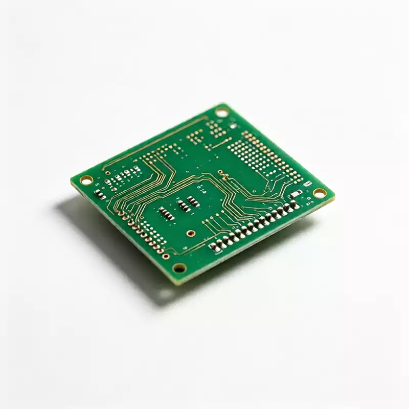
An HDI PCB and a standard multilayer PCB can use exactly the same schematic and perform the same basic electrical functions, yet they may not be equally suitable for a particular product. The difference is not simply a matter of manufacturing quality or whether one PCB technology appears more advanced than the other. The real difference lies in how the PCB construction manages routing density, interlayer connections, signal integrity, component fan-out, manufacturing complexity, and overall system cost.
The choice between an HDI PCB and a conventional multilayer PCB should therefore be made during the early stages of hardware development, before the PCB stackup and layout are frozen. Once the layer structure, via technology, component placement, and board outline have been finalized, changing the PCB construction can require significant redesign work.
This guide explains the practical differences between HDI PCB and standard multilayer PCB technology and provides engineering criteria for determining which construction is more appropriate for a specific application. The focus is on the factors that have the greatest impact on PCB design and manufacturing, including BGA pitch, routing density, layer count, high-speed signal requirements, microvia structures, sequential lamination, via-in-pad technology, manufacturing capability, cost, and long-term reliability.
The objective is not to treat HDI as a universally superior PCB technology. Instead, the goal is to determine whether the additional manufacturing complexity of HDI provides a measurable benefit for the specific design.
HDI PCB vs. Standard Multilayer PCB: The Core Structural Difference
The fundamental difference between an HDI PCB and a standard multilayer PCB is the way electrical connections are made between PCB layers.
A conventional multilayer PCB primarily relies on through-hole vias that are mechanically drilled through the entire PCB thickness. A plated through-hole can electrically connect multiple layers, but the drilled hole and its associated pad structure occupy routing space on every layer that the via passes through. Even when a signal only needs to connect between two adjacent layers, a conventional through-hole may extend through the entire board.
This creates a significant limitation in high-density layouts. The via barrel and surrounding clearance consume routing space on multiple layers, and unused portions of the via barrel can also create electrical discontinuities or via stubs that become increasingly important as signal frequency and data rate increase.
An HDI PCB, by contrast, uses laser-drilled microvias and build-up dielectric layers to create shorter interconnections between adjacent or nearby copper layers. Instead of relying exclusively on a mechanically drilled hole that passes through the complete board, an HDI structure can use a microvia that connects only the layers required by the circuit.
The resulting structure can significantly improve routing density. In a dense BGA fan-out region, for example, microvias can be positioned within or near component pads, allowing traces to escape from fine-pitch packages without consuming as much routing area as conventional through-hole vias.
This is the fundamental value proposition of HDI technology: it increases usable routing density by changing the way layers are interconnected.
However, HDI should not be viewed simply as a premium version of a conventional multilayer PCB. HDI introduces additional manufacturing processes, tighter registration requirements, and more demanding process control. The engineering decision is therefore a trade-off between routing density and manufacturing complexity.
If a conventional multilayer PCB can meet the required electrical and mechanical specifications without excessive layer count or routing compromises, HDI may provide little practical benefit. If the conventional construction cannot accommodate the required component density or routing architecture, HDI can become an effective solution.
Choose HDI Based on Routing Density, Not Product Prestige
One of the most common mistakes in PCB development is treating HDI as a general-purpose upgrade. In reality, HDI PCB technology is designed to solve specific physical and electrical constraints, particularly those associated with fine-pitch components, high routing density, limited PCB area, and high-speed interconnects.
A useful engineering question is therefore not “Is HDI better?” but rather:
What specific design constraint does HDI solve in this PCB?
If the PCB layout can be completed comfortably using the planned layer count, component pitch, via structure, and signal-integrity requirements, adopting HDI may add manufacturing cost without providing a corresponding product-level benefit.
On the other hand, if the design requires additional PCB layers solely to complete BGA fan-out, or if the board outline cannot be increased to accommodate conventional routing, HDI may allow the same functionality to be achieved with a more compact layer structure.
This distinction is particularly important in cost-sensitive products. Engineering teams sometimes specify HDI because it was used successfully on a previous product or because a high-density PCB is automatically associated with advanced technology. However, if the additional routing capability is not actually required by the final layout, the project may incur higher manufacturing costs and tighter process constraints without gaining a measurable system-level advantage.
Three Practical Criteria for Selecting HDI or Standard Multilayer PCB
A practical PCB construction decision can often be narrowed down by evaluating three factors early in the project: BGA pad pitch, potential layer reduction, and per-lane data rate.
These are not absolute industry rules. They are engineering reference points that can help identify whether the design requires further HDI evaluation.
- BGA Pad Pitch and Fan-Out Requirements
BGA pitch is one of the most important factors when evaluating an HDI PCB.
When the BGA pitch becomes very fine, conventional through-hole vias and dog-bone fan-out patterns can consume too much routing space around the component pads. The available mechanical clearance becomes increasingly restrictive, making it difficult to escape inner BGA rows without adding additional routing layers.
At pitches below approximately 0.65 mm, conventional through-hole fan-out can become highly constrained, depending on the package geometry, pad diameter, via diameter, PCB material construction, and fabrication capability. Laser-drilled microvias, particularly via-in-pad structures with filled and capped microvias, can provide a practical solution for dense BGA fan-out.
At approximately 0.8 mm BGA pitch, conventional through-hole fan-out can still be feasible for many designs. However, an HDI construction may reduce the number of PCB layers required for routing, especially when the conventional design would otherwise need additional fan-out layers.
At 1.0 mm pitch and above, conventional multilayer PCB construction is often capable of accommodating BGA fan-out without requiring HDI, although the actual result still depends on package dimensions, pad size, via rules, trace width, and board-level routing density.
The key point is that BGA pitch should not be evaluated in isolation. The actual decision depends on the relationship between BGA pitch, pad geometry, via diameter, trace width, spacing, and available routing layers.
- Potential Reduction in PCB Layer Count
The second useful criterion is to determine how many PCB layers are required solely because of component fan-out.
Suppose a conventional multilayer design requires several additional layers simply to escape a fine-pitch BGA. In that situation, it is worth comparing the total manufacturing cost of the conventional stackup with an HDI stackup that uses microvias and sequential lamination to achieve the same routing density.
If an HDI construction eliminates several routing layers, the higher process cost associated with HDI may be partially or completely offset by the reduction in total layer count.
If the HDI design does not eliminate meaningful routing layers, however, the additional microvia, laser-drilling, lamination, plating, filling, and inspection processes may increase the PCB cost without producing a corresponding benefit.
For this reason, engineers should compare complete PCB constructions rather than comparing the nominal price of one HDI layer with one conventional layer.
- High-Speed Data Rate and Via Stub Length
High-speed interfaces introduce another important consideration because conventional through-hole vias can create unwanted via stubs.
A through-hole via that extends beyond the layer where the signal terminates creates an electrically unused section of the via barrel. At lower frequencies, this may have limited impact. As signal rise time becomes faster and data rates increase, however, the via stub can behave as a significant transmission-line discontinuity and contribute to reflections, resonances, and insertion-loss degradation.
For many interfaces below approximately 5 Gbps, a properly designed conventional through-hole via can still provide acceptable signal-integrity performance, provided that the stackup, via geometry, reference planes, and routing are appropriately engineered.
Between approximately 5 and 10 Gbps, back-drilling or other stub-reduction techniques can often be used to improve the performance of conventional through-hole vias without converting the entire PCB to an HDI construction.
At higher data rates, especially above approximately 10 Gbps, minimizing via stubs becomes increasingly important. Microvias can provide very short vertical interconnections and therefore offer an attractive solution for high-speed differential signaling.
These values should be treated as practical engineering reference points rather than rigid design rules. Actual requirements depend on signal rise time, channel length, dielectric material, stackup, via geometry, transmitter and receiver characteristics, and the specific interface standard.
What Does an HDI PCB Actually Add to the Manufacturing Process?
The routing benefits of HDI come with additional manufacturing complexity.
A conventional multilayer PCB can often be fabricated using a relatively straightforward sequence of lamination, mechanical drilling, plating, imaging, etching, solder mask, and surface-finish processes.
An HDI PCB introduces additional build-up layers and frequently requires sequential lamination, laser drilling, microvia formation, copper plating, microvia filling, planarization, and additional registration control.
Each build-up cycle introduces another opportunity for dimensional variation. Material movement, registration drift, dielectric thickness variation, copper distribution, and process tolerances can accumulate across multiple lamination cycles.
As HDI structures become more complex, the PCB manufacturer must also control scaling factors, optical target registration, copper balance, laser-drilling parameters, via-fill performance, and interlayer alignment with greater precision.
This is one reason why not every PCB manufacturer has the same HDI capability. A factory capable of producing conventional six-layer or eight-layer PCBs is not automatically qualified to manufacture complex stacked-microvia HDI boards.
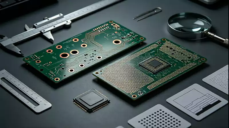
HDI PCB Cost: How Much More Does HDI Cost?
There is no universal percentage that can accurately describe the cost premium of every HDI PCB.
The final PCB price depends on the specific stackup, number of sequential lamination cycles, microvia architecture, via filling requirements, copper thickness, board size, panel utilization, surface finish, inspection requirements, production volume, and manufacturer capability.
As a general commercial reference, a relatively simple 1+N+1 HDI construction may carry a manufacturing premium compared with an equivalent conventional multilayer PCB. More complex structures, such as 2+N+2 stacked microvia constructions or any-layer HDI, can introduce substantially higher process costs.
Rather than assuming a fixed HDI markup, engineers should obtain parallel quotations from qualified manufacturers using the same PCB design requirements.
The comparison should include the complete construction rather than only the bare-board unit price. In some applications, an HDI PCB can reduce the total number of layers, PCB dimensions, connector count, enclosure size, or assembly complexity. These system-level savings can offset part of the additional HDI manufacturing cost.
Therefore, the correct question is not simply:
“How much more does an HDI PCB cost?”
The more useful question is:
“What system-level value does the HDI construction provide compared with the conventional alternative?”
When an HDI PCB Can Provide System-Level Value
HDI technology becomes particularly attractive when it solves a physical or electrical constraint that cannot be addressed economically with conventional PCB construction.
Limited PCB Footprint
When the PCB outline is constrained by an enclosure, connector arrangement, display module, battery compartment, or mechanical assembly, increasing the board size may not be possible.
In this situation, HDI can increase routing density within the existing board area. A smaller PCB may also reduce enclosure size, connector requirements, cable length, or assembly complexity, creating savings beyond the bare PCB itself.
Fine-Pitch BGA Components
Fine-pitch BGA packages are one of the most common reasons for adopting HDI.
If conventional through-hole fan-out requires additional routing layers, while microvia-based fan-out allows the same BGA to escape within a smaller build-up structure, HDI can reduce routing complexity and potentially reduce the overall layer count.
High-Speed Interconnects
HDI can also benefit high-speed designs by reducing via stub length and shortening vertical interconnects.
However, HDI does not automatically guarantee better signal integrity. The final electrical performance still depends on the complete PCB stackup, dielectric properties, reference-plane continuity, trace geometry, via transitions, return-current paths, and channel design.
High-Density Mixed-Signal Designs
Compact products that combine RF, digital, analog, power, and high-speed interfaces may benefit from the routing density provided by HDI.
However, mixed-signal performance still depends on appropriate grounding, plane partitioning strategy, return-current control, electromagnetic isolation, and stackup design. HDI should be viewed as a routing technology rather than a substitute for sound signal-integrity and EMC design practices.
When a Standard Multilayer PCB Is the More Practical Choice
A standard multilayer PCB remains the appropriate solution for many commercial, industrial, and embedded products.
Conventional construction is often sufficient when the layout can be completed comfortably within the target layer count, the minimum BGA pitch is relatively generous, the PCB footprint is not severely constrained, and the signal-integrity requirements can be satisfied using conventional vias and appropriate stackup design.
Standard multilayer PCBs can also provide significant advantages for cost-sensitive products, particularly when production volumes are low or medium and the additional HDI process overhead cannot be efficiently amortized.
High-Current PCB Applications
Power electronics and high-current applications are another area where conventional multilayer construction can be advantageous.
Heavy-copper PCBs, large plated through-holes, robust via structures, and wider conductors may be more appropriate for high-current applications than very small HDI microfeatures.
The larger via structures used in conventional PCBs can also simplify prototype modification, manual rework, component replacement, and field service.
Supplier Availability and Manufacturing Risk
Conventional multilayer PCB technology is supported by a broader range of PCB manufacturers than advanced HDI structures.
A wider supplier base can provide greater flexibility in terms of lead time, production capacity, qualification, and commercial negotiation. For products where HDI does not solve a critical design constraint, this manufacturing flexibility can be an important consideration.
Microvia Structures and HDI PCB Reliability
Not all microvia structures have the same manufacturing and reliability characteristics. The two commonly discussed configurations are staggered microvias and stacked microvias.
Staggered Microvias
Staggered microvias are offset horizontally between adjacent build-up layers rather than being placed directly on top of one another.
This configuration generally provides a more forgiving manufacturing process because each microvia is not dependent on a vertically aligned interface with another microvia beneath it.
Staggered structures can reduce the difficulty associated with microvia filling and registration and can provide greater manufacturing margin when sufficient routing space is available.
For demanding applications such as automotive electronics, medical devices, aerospace systems, and long-life industrial equipment, the microvia architecture should be selected based on the required reliability, manufacturing capability, thermal cycling conditions, and product lifetime.
Stacked Microvias
Stacked microvias allow multiple microvias to be vertically aligned and stacked between build-up layers. This structure provides excellent routing density and is particularly useful for fine-pitch BGA fan-out.
However, stacked microvias introduce additional process dependencies. The lower microvia must be properly filled and planarized before another microvia can be formed on top of it.
The reliability of a stacked microvia structure therefore depends heavily on copper filling quality, plating integrity, planarization, registration accuracy, and control of the thermal-mechanical stresses generated during assembly and operation.
Simply specifying “stacked microvias” does not guarantee reliability. The entire fabrication process must be properly controlled and validated.
Via-in-Pad Requirements for Fine-Pitch BGA Packages
Via-in-pad is a key HDI technology for fine-pitch BGA fan-out because it places the microvia directly within the component pad instead of routing the connection outward through a conventional dog-bone structure.
For via-in-pad applications, the PCB fabrication drawing should clearly define the required microvia filling, copper capping, and surface planarization process.
If a via beneath a BGA pad is not properly filled and sealed, solder can migrate into the via during reflow. This phenomenon, commonly referred to as solder wicking, can reduce the solder volume available at the joint and potentially contribute to solder-joint reliability problems.
For this reason, via-in-pad should not be treated simply as a layout feature. It is a manufacturing process requirement that must be explicitly defined and validated with the PCB fabricator.
How to Verify a PCB Manufacturer’s HDI Capability
Not every PCB manufacturer has the same HDI manufacturing capability.
A supplier may be capable of producing basic laser-drilled microvias but lack the process maturity required for stacked microvias, multiple sequential lamination cycles, or advanced any-layer HDI structures.
Before awarding production, hardware engineers should verify the manufacturer’s actual production capability rather than relying solely on a general statement that the supplier “supports HDI.”
Important qualification questions include whether the manufacturer operates its own CO₂ or UV laser drilling equipment, how many sequential lamination cycles are routinely supported in mass production, what accumulated layer-registration tolerance can be achieved, and what process is used for microvia copper filling and surface planarization.
It is also important to understand what production inspection data will be provided with each lot.
Depending on the application, useful manufacturing evidence can include X-ray registration data, microsection analysis, process coupons, electrical continuity and resistance measurements, and controlled-impedance test results based on the actual production stackup.
The manufacturer and customer should agree on acceptance criteria before production release. This should include the required thermal exposure conditions, test coupon construction, sampling plan, microsection requirements, and electrical test criteria.
Electrical continuity testing alone cannot identify every latent interlayer defect. Some manufacturing defects may only become apparent after reflow, thermal cycling, or mechanical stress. For demanding applications, reliability validation should therefore be incorporated into the qualification plan.
Frequently Asked Questions About HDI PCB and Standard Multilayer PCB
At What BGA Pitch Is HDI Required?
There is no single BGA pitch at which HDI becomes universally mandatory because the actual requirement depends on pad diameter, via size, trace width, spacing, package geometry, and PCB fabrication capability.
Below approximately 0.65 mm pitch, conventional through-hole fan-out can become highly restrictive, and filled microvias with via-in-pad may provide a practical solution. At around 0.8 mm pitch, conventional construction may still be feasible, although HDI can sometimes reduce the required layer count.
How Much More Expensive Is an HDI PCB?
HDI pricing varies significantly between manufacturers and construction types. Simple build-up structures may have a moderate premium over equivalent conventional multilayer PCBs, while complex stacked-microvia or any-layer HDI structures can have substantially higher manufacturing costs.
The most reliable approach is to obtain parallel quotations for both constructions using the same board outline, copper weights, material requirements, surface finish, production volume, and inspection criteria.
Does HDI Automatically Improve Signal Integrity?
No. HDI can improve certain high-speed characteristics by reducing via stub length and shortening vertical interconnections, but the final signal-integrity performance depends on the complete interconnect structure.
Stackup design, dielectric properties, reference-plane continuity, trace geometry, via transitions, return paths, connector characteristics, and channel length all contribute to the final result.
Are Microvias Reliable for Long-Life Products?
Microvias can provide reliable performance when their geometry, copper plating, filling process, registration, and thermal-mechanical design are properly controlled.
The reliability of a microvia structure should be evaluated based on the intended application, thermal cycling conditions, manufacturing process, and expected product lifetime. Staggered microvias can provide greater manufacturing margin than some stacked structures, but the actual reliability depends on the complete process and design.
When Should I Use a Standard Multilayer PCB Instead of HDI?
A conventional multilayer PCB is generally worth considering when the required fan-out can be completed without adding dedicated routing layers, the BGA pitch and routing density are manageable, the PCB footprint is not severely constrained, and the application places strong emphasis on cost, lead time, heavy copper, or ease of rework.
Can a Standard Multilayer PCB Replace an HDI PCB?
In many applications, yes. If the PCB provides sufficient routing space and the component fan-out can be completed using conventional through-hole vias or other appropriate via structures, an HDI construction may not be necessary.
A DFM review with the PCB manufacturer before the layout is frozen is one of the most effective ways to determine whether conventional multilayer construction can meet the actual manufacturing requirements.
Can Every PCB Manufacturer Build HDI PCBs?
No. HDI manufacturing requires specific capabilities, including laser drilling, sequential lamination, microvia formation and filling, accurate multilayer registration, and appropriate inspection processes.
The more complex the HDI structure becomes, the more important it is to verify the manufacturer’s demonstrated production experience rather than relying only on its published capability list.
HDI PCB vs. Standard Multilayer PCB: Final Design Considerations
The decision between an HDI PCB and a standard multilayer PCB should be made while the PCB stackup and mechanical architecture are still flexible.
Start by evaluating the BGA pitch and fan-out requirements, then determine whether a conventional construction requires additional layers solely to accommodate component escape routing. After that, evaluate the signal-integrity requirements, particularly for high-speed interfaces where via stubs and vertical interconnect transitions may become significant.
If HDI eliminates several routing layers, reduces the PCB footprint, enables a fine-pitch BGA that cannot be routed conventionally, or provides a meaningful high-speed interconnect advantage, the additional manufacturing complexity may be justified.
If the PCB can be routed comfortably using a conventional multilayer stackup, adopting HDI simply because it is considered a more advanced technology can introduce unnecessary manufacturing cost, tighter process tolerances, a smaller qualified supplier base, and additional production risk.
Two common mistakes should therefore be avoided.
The first is over-specifying HDI. This occurs when a design could be manufactured successfully using a standard multilayer PCB but HDI is selected without a specific engineering requirement. The result can be higher manufacturing cost and process complexity without a corresponding product benefit.
The second is under-specifying the PCB construction. This occurs when the design team waits until after the PCB layout is frozen to discover that BGA fan-out, routing density, board size, or high-speed interconnect requirements cannot be achieved with the original stackup. Correcting the problem at that stage may require additional layers, a larger PCB outline, component relocation, or a complete PCB redesign.
The most cost-effective approach is therefore to evaluate HDI PCB and standard multilayer PCB construction before the PCB stackup and layout are finalized. Compare both technologies using the same electrical requirements, board dimensions, component placement, layer-count assumptions, material specifications, and manufacturing volume.The goal is not to select the more sophisticated PCB technology. The goal is to select the simplest PCB construction that reliably satisfies the electrical, mechanical, manufacturing, and cost requirements of the product.