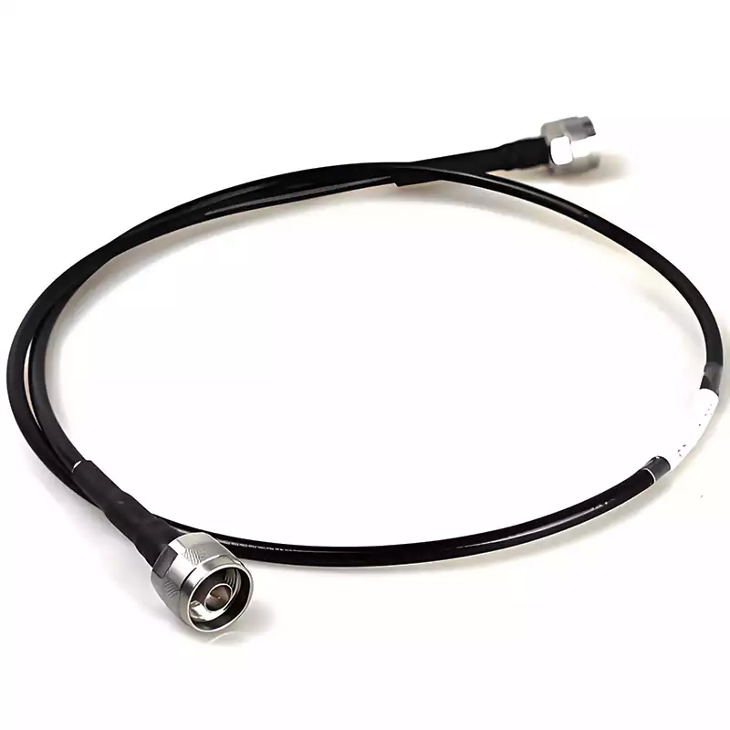
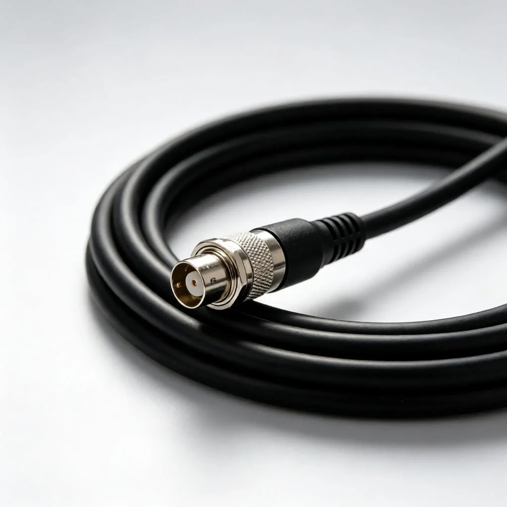
50 ohm RF cable, full name 50 ohm characteristic impedance coaxial RF cable, is a coaxial transmission wire specially used for transmitting high-frequency radio frequency (RF) electromagnetic wave signals, serving as the core transmission medium in RF systems. The 50 ohm rating of 50 ohm RF cables does not produce any special physical effect by itself.
Instead, the coaxial structure guides the transmission of transverse electromagnetic (TEM) mode electromagnetic waves. The “50 ohm” refers to characteristic impedance, an inherent property determined by the geometric dimensions of conductors and dielectric parameters. It is applied to achieve impedance matching among signal sources, transmission lines and loads, so as to minimize signal reflection while balancing power handling capacity and transmission loss.
The operating principle of 50 ohm RF coaxial cables mainly relies on three core mechanisms: coaxial electromagnetic wave transmission, impedance matching and electromagnetic shielding, which enable high-efficiency, low-loss and reflection-free transmission of high-frequency/microwave signals.
Coaxial Transmission Mechanism (Principles of Electromagnetic Wave Propagation)
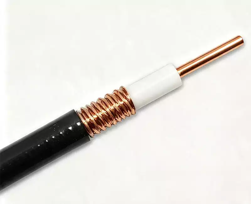
Structural composition: The cable consists of an inner conductor (central copper wire), insulating dielectric (filling layer between inner and outer conductors), outer conductor (metallic shielding layer) and outer sheath. The inner and outer conductors are arranged concentrically.
Transmission mode: Electromagnetic waves (TEM mode), rather than directional electron flow for direct current or low-frequency signals, propagate inside the cable. Electromagnetic waves are strictly confined within the insulating dielectric region between the inner and outer conductors. The electric field extends from the outer surface of the inner conductor to the inner surface of the outer conductor, while the magnetic field surrounds the inner conductor.
Advantages: The coaxial structure confines electromagnetic fields inside the cable, effectively preventing signal radiation leakage and protecting signals from external electromagnetic interference (EMI).
Impedance Matching Mechanism (Principles of Signal Transmission Efficiency)
Definition of characteristic impedance: The characteristic impedance (Z₀) of an RF cable is an inherent property, determined jointly by the outer diameter of the inner conductor (d), the inner diameter of the outer conductor (D) and the relative permittivity (εᵣ) of the insulating dielectric (Formula: Z₀ = (138 / √εᵣ) × log(D/d)).
The compromise rationale for 50 ohm: 50 ohm is an engineering optimal compromise value. Theoretical calculations indicate that coaxial cables achieve maximum power handling capacity (high voltage resistance) at 30 Ω and minimum signal transmission loss at 77 Ω. Sitting between these two values, 50 ohm balances power transmission efficiency and signal loss. Meanwhile, it matches the port impedance of most RF devices such as antennas and amplifiers.
Functions of impedance matching: When full impedance matching is achieved between the signal source, 50 ohm cable characteristic impedance and load impedance, all signal energy can be delivered to the load without reflection to realize maximum power transfer. In the event of impedance mismatch, part of the signal reflects back toward the source, forming standing waves and resulting in signal distortion and power loss.
Electromagnetic Shielding Mechanism (Anti-Interference Principle)
Functions of the outer conductor (shielding layer): The outer conductor (such as braided copper mesh or aluminum foil) acts not only as the return path for signals but also forms a complete electromagnetic shielding barrier. It isolates the internally transmitted electromagnetic fields from the external environment, preventing signal crosstalk and external interference and ensuring signal transmission purity.
Why Select 50 ohm RF Cables?
1.Perspective of PCB Manufacturing Process
From the perspective of PCB fabrication, producing PCBs with controlled 50 ohm impedance is relatively feasible for most existing PCB manufacturers with standard equipment.
According to impedance calculation, lower impedance requires wider trace widths, thinner dielectrics or higher permittivity materials, which are difficult to implement within limited space for high-density circuit boards.
Conversely, higher impedance demands narrower traces, thicker dielectrics or low-permittivity materials. This hinders the suppression of EMI and crosstalk, and leads to poor manufacturing reliability for multilayer boards in mass production.
When controlling impedance at 50 ohm, common board materials (FR-4, RO4350B, etc.) and standard core materials can be adopted for products with conventional board thicknesses (e.g., 0.508 mm, 1 mm, 1.2 mm). Trace widths ranging from 4 mil to 10 mil can be adopted, facilitating mass fabrication by PCB factories without stringent requirements on production equipment.
2.Perspective of PCB Design
50 ohm is also a choice derived from comprehensive design trade-offs. As shown in impedance calculation, for traces with fixed width, thinner board dielectric corresponds to lower impedance. Three major factors affect the impedance of PCB traces.
First, the near-field EMI of PCB traces is proportional to the height between microstrip traces and the reference plane (ground plane). Lower height brings weaker electromagnetic radiation.
Second, crosstalk varies significantly with trace height. If the height is halved, crosstalk is reduced to nearly one quarter of the original level.
Third, lower height leads to lower impedance, making traces less susceptible to capacitive load effects.
Perspective of Full Signal Path
Designers must also consider chip driving capability, the most critical factor. In the early stages, most chips could not drive transmission lines with impedance below 50 ohm, while higher-impedance transmission lines faced implementation obstacles. Therefore, 50 ohm was selected as a compromised solution.
Perspective of Electrical Performance
The skin effect exists in high-frequency and high-speed circuits. The industry has verified that 50 ohm yields minimum loss in consideration of the skin effect. Generally, the skin effect loss L of a cable (in decibels) is proportional to the ratio between total unit-length skin resistance R and characteristic impedance Z₀.
The total skin resistance R equals the sum of the resistance of the shielding layer and the inner conductor.
At high frequencies, the skin effect resistance of the shielding layer is inversely proportional to its outer diameter d₂, and the skin effect resistance of the inner conductor is inversely proportional to its diameter d₁. The overall series resistance R is thus proportional to (1/d₂ + 1/d₁).
With all factors taken into account, given fixed d₂ and relative permittivity εᵣ of the dielectric material, the ratio d₂/d₁ that minimizes skin effect loss can be calculated. Assuming solid polyethylene with relative permittivity of 2.25, the optimal ratio d₂/d₁ for minimum skin loss equals 3.5911, which corresponds exactly to a characteristic impedance of 50 ohm.
Features of 50 ohm RF Cables
(1) Characteristic Impedance: 50 ohm coaxial cables feature 50 ohm characteristic impedance, suitable for high-frequency signal transmission. Compared with 75 Ω coaxial cables, 50 ohm cables deliver superior performance in power transmission and low-loss transmission.
(2) Low Loss: 50 ohm coaxial cables maintain low signal loss during high-frequency signal transmission, ensuring signal integrity and clarity.
(3) Anti-Interference Performance: Benefiting from shielding layer design, 50 ohm coaxial cables effectively resist external electromagnetic interference and guarantee stable signal transmission.
(4) Flexibility: Coaxial cables feature relatively good flexibility for convenient installation and routing, and can be deployed in various complex environments.
Differences between 50 Ohm and 75 Ohm RF Cables
| Comparison Dimension | 50 Ohm RF Cable | 75 Ohm RF Cable |
|---|---|---|
| Core Advantages | High power capacity, superior anti-reflection performance, compatible with RF equipment | Ultra-low transmission loss, outstanding performance for long-distance transmission |
| Disadvantages | Slightly higher attenuation than 75 Ω cables over long distances | Unable to withstand high power; prone to standing wave distortion |
| Primary Applications | Wireless communication, signal transmission, RF testing | Video transmission, cable television, surveillance signal transmission |
| Common Models | RG174, RG58, RG213, 1/2″, 7/8″, 1-5/8″ feeder cables | RG59, RG6, SYV75-5, SYWV75-7 |
| Common Connectors | SMA, Type N, RF BNC, UHF connectors | F-type connectors, video-grade BNC connectors |
| Matched Equipment | Base stations, wireless bridges, walkie-talkies, spectrum analyzers, antennas | Surveillance cameras, set-top boxes, televisions, satellite receivers |
Common Specifications and Parameters of 50 Ohm RF Cables
1.Flexible Standard Jumper Cables (Short-range Indoor Deployment)
RG174: Thinnest outer diameter, flexible and portable with relatively high attenuation. Suitable for short inter-module wiring and internal equipment cabling; recommended transmission distance ≤ 5 m.
RG58: Universal engineering-grade cable with favorable cost performance, balancing attenuation and flexibility. Ideal for wireless bridges, walkie-talkies and general antenna jumpers.
RG213: Large conductor size, high power rating and low attenuation, applied for short-distance high-power RF transmission outdoors.
2.Semi-rigid / Semi-flexible Cables (Precision Equipment)
50-047, 50-086: Excellent shape retention, superior shielding performance and ultra-low signal attenuation. Widely adopted inside RF test instruments, base station modules and precision RF equipment.
3.Corrugated Base Station Feeder Cables (Long-distance Outdoor Installation)
1/2″, 7/8″, 1-5/8″ feeder cables: Constructed with rigid corrugated copper tubes. Featuring exceptional shielding, low attenuation and high power handling capacity, they serve as the primary cabling solution for long-distance wiring of 4G/5G macro outdoor base stations.
Application Fields of 50 Ohm RF Cables
Mobile Communication Base Stations: Feeders and jumpers for 4G/5G macro base stations, micro base stations and indoor distributed antenna systems;
Wireless Communication Equipment: Walkie-talkies, vehicle-mounted radios, Wi-Fi / 6G wireless bridges, IoT gateways, drone video transmission systems;
RF Testing Industry: Test cables for signal generators, spectrum analyzers and vector network analyzers;
Industrial and Special Scenarios: Rail transit communication, marine navigation, radar equipment, wireless security monitoring;
Civil DIY Scenarios: Wireless antenna modification, amateur radio, wiring for RF modules.
Key Considerations for Selection and Deployment of 50 Ohm Coaxial Cables
(1) Select appropriate cable type: Choose a suitable type of 50 Ohm coaxial cable according to practical application requirements. Different cable variants meet distinct frequency and power specifications.
(2) Pay attention to cable length: Cable length contributes to signal attenuation. Minimize cable length to reduce transmission loss.
(3) Connector selection: Always deploy impedance-matched connectors when terminating 50 Ohm coaxial cables to prevent signal reflection and extra loss.
(4) Periodic inspection: Regularly check cable integrity and connection status to guarantee stable signal transmission.
50 ohm RF cables are standardized transmission lines in the radio frequency sector that balance power handling capacity, transmission loss and engineering practicality. Thanks to their balanced electrical performance and impedance characteristics compatible with most RF equipment, they have become the mainstream choice for scenarios such as wireless communication and RF testing.